Hi VZS, zinsula
As the 'official' testers") it would be interesting to hear what improvements the addition of the driver board has had on your systems.
it would be interesting to hear what improvements the addition of the driver board has had on your systems.
Have either of you had a chance for some detailed listening to describe what changes (major or minor) the board brings to your sound as yet?
Thanks
As the 'official' testers
it would be interesting to hear what improvements the addition of the driver board has had on your systems. Have either of you had a chance for some detailed listening to describe what changes (major or minor) the board brings to your sound as yet?
Thanks
TOTAL = 41
TV Man x 2
merlin el mago
rtd
jameshillj
erin
Nikola Krivorov x 3
Rupor54
vitalica
analog_sa
andrea_mori x 5
dsavitsk
tagheuer
hirez69 x 2
ccliu
BDL
cddumat
regal
zoran
Jogi
Zen(zenelectro) x 2
Buzzforb
SPWON
crobbins5421
marcus1 X 2
casshan x 2
Dweeb99 X 2
jackw X 2
kazap X 2
TV Man x 2
merlin el mago
rtd
jameshillj
erin
Nikola Krivorov x 3
Rupor54
vitalica
analog_sa
andrea_mori x 5
dsavitsk
tagheuer
hirez69 x 2
ccliu
BDL
cddumat
regal
zoran
Jogi
Zen(zenelectro) x 2
Buzzforb
SPWON
crobbins5421
marcus1 X 2
casshan x 2
Dweeb99 X 2
jackw X 2
kazap X 2
Being a glue logic board it shouldn't add anything to the system but it should be as transparent as possible and I think this board does this excellently. As I said couple of pages ahead it works flawlessly from 44.1K to 192K I tested.Hi VZS, zinsula
As the 'official' testers
Have either of you had a chance for some detailed listening to describe what changes (major or minor) the board brings to your sound as yet?
Thanks
Compared to my previous glue logic with HC164s and HC374 it is much-much better - but that had several design flaws especially regarding the PCB routing.
I already forgot it's integrated into my system as I was focusing onto the I/V stage
Being a glue logic board it shouldn't add anything to the system but it should be as transparent as possible and I think this board does this excellently. As I said couple of pages ahead it works flawlessly from 44.1K to 192K I tested.
Compared to my previous glue logic with HC164s and HC374 it is much-much better - but that had several design flaws especially regarding the PCB routing.
I already forgot it's integrated into my system as I was focusing onto the I/V stage
Thank vzs for confirming AD1865 works properly with the I2S-PCM daughter board, at continue/stoped clock mode and from 44.1Khz to 192Khz.
If it is possible, I'd be glad to see some pictures of your setup
.Merry Christmas!
Ian
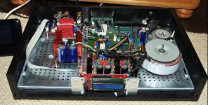
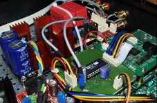
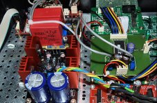
So here comes the mass I call my DAC
From top-left to bottom-right the modules are:
- r2r volume control and input selection connected to the controller with LCD from middle-bottom
- dual Salas shunt regs from a DCB1 Hypnotize board and a Pass D1 I/V converter to fit over the empty space of the Hypnotize board
- yummy DAC and FIFO sandwich the temporary DAC PCB one day will be replaced with one containing a selectable digital filter (DF1706) when the source is 44.1Khz (CD). Before somebody complains: 0603|0805 decoupling caps are on the bottom of the DAC board
- bottom of DAC sandwich are 3 Salas shunts feeding the AD1865. When the digital isolator will be ready one of them will also fed the clock and I2S-to-PCM board
- then comes a SPDIF receiver with CS8416 connected to a SPDIF buffer (Jocko like) that is on the back side of the veroboard with the BNCs
- finally a 5V prereg for the FIFO and some shielded over-sized toroids
What is on the workbench:
- another DCB1 Hypnotize board to have a buffer after the volume controller
- your digital isolator board
- small selector to switch between two I/Vs
Thanks, Zsolt
From top-left to bottom-right the modules are:
- r2r volume control and input selection connected to the controller with LCD from middle-bottom
- dual Salas shunt regs from a DCB1 Hypnotize board and a Pass D1 I/V converter to fit over the empty space of the Hypnotize board
- yummy DAC and FIFO sandwich
the temporary DAC PCB one day will be replaced with one containing a selectable digital filter (DF1706) when the source is 44.1Khz (CD). Before somebody complains: 0603|0805 decoupling caps are on the bottom of the DAC board - bottom of DAC sandwich are 3 Salas shunts feeding the AD1865. When the digital isolator will be ready one of them will also fed the clock and I2S-to-PCM board
- then comes a SPDIF receiver with CS8416 connected to a SPDIF buffer (Jocko like) that is on the back side of the veroboard with the BNCs
- finally a 5V prereg for the FIFO and some shielded over-sized toroids
What is on the workbench:
- another DCB1 Hypnotize board to have a buffer after the volume controller
- your digital isolator board
- small selector to switch between two I/Vs
Thanks, Zsolt
Attachments
Last edited:
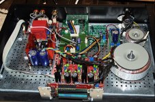
So here comes the mass I call my DAC
From top-left to bottom-right the modules are:
- r2r volume control and input selection connected to the controller with LCD from middle-bottom
- dual Salas shunt regs from a DCB1 Hypnotize board and a Pass D1 I/V converter to fit over the empty space of the Hypnotize board
- yummy DAC and FIFO sandwich
- bottom of DAC sandwich are 3 Salas shunts feeding the AD1865. When the digital isolator will be ready one of them will also fed the clock and I2S-to-PCM board
- then comes a SPDIF receiver with CS8416 connected to a SPDIF buffer (Jocko like) that is on the back side of the veroboard with the BNCs
- finally a 5V prereg for the FIFO and some shielded over-sized toroids
What is on the workbench:
- another DCB1 Hypnotize board to have a buffer after the volume controller
- your digital isolator board
- small selector to switch between two I/VsSa
Thanks, Zsolt
Hi Zsolt,
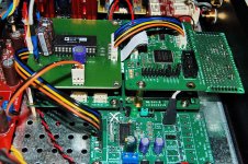
Your DAC looks great! It's amazing how you could fit everything into a very compact space. You have SPDIF interface, FIFO, clock, daughter board, AD1865, D1 IV,shunt regs, controller with LCD... almost everything
.I like your 1865 core board, looks very clean, I almost couldn't help...
Why my Salas shunt reg is much bigger than yours? As well as my D1 I/V. Did I miss some wonderful group buy? What is the Hypnotize board? I'm interested in the board.Can you give me a bit more details?
Thanks Zsolt for sharing pictures of your system with us. It seems I need take some time to get understand every details
.Merry Christmas

Ian
Why my Salas shunt reg is much bigger than yours? As well as my D1 I/V. Did I miss some wonderful group buy? What is the Hypnotize board? I'm interested in the board.Can you give me a bit more details?
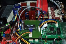
because his is part of the hypnotise board, which does not permit as much flexibility, or as high voltage (without modifications) its similar to the hotrod DCB1. it has an analogue stage on there, along with the regs, but many ended up just building the regs with it to power other things, which without using the free space like he has, makes them larger, not smaller.
His version of the D1 is much lower voltage and lower current, thus smaller, hes not even using heatsinks at all.... I admit its very cool indeed fitting in the empty space like that, neat idea, but in the NTD1 development thread you can see how profoundly different the performance is with NTD1 and ESS to stock D1 and ESS, no way in hell it will fit in that space. NTD1 uses no buffer but MUCH higher class A bias at more than double the voltage to push the transconductance of the mosfets up and thus bring the impedance down along with THD to match. this brute force uses space
me included ...
TOTAL = 42
TV Man x 2
merlin el mago
rtd
jameshillj
erin
Nikola Krivorov x 3
Rupor54
vitalica
analog_sa
andrea_mori x 5
dsavitsk
tagheuer
hirez69 x 2
ccliu
BDL
cddumat
regal
zoran
Jogi
Zen(zenelectro) x 2
Buzzforb
SPWON
crobbins5421
marcus1 X 2
casshan x 2
Dweeb99 X 2
jackw X 2
kazap X 2
danzup
TOTAL = 42
TV Man x 2
merlin el mago
rtd
jameshillj
erin
Nikola Krivorov x 3
Rupor54
vitalica
analog_sa
andrea_mori x 5
dsavitsk
tagheuer
hirez69 x 2
ccliu
BDL
cddumat
regal
zoran
Jogi
Zen(zenelectro) x 2
Buzzforb
SPWON
crobbins5421
marcus1 X 2
casshan x 2
Dweeb99 X 2
jackw X 2
kazap X 2
danzup
Default me included ...
TOTAL = 44
TV Man x 2
merlin el mago
rtd
jameshillj
erin
Nikola Krivorov x 3
Rupor54
vitalica
analog_sa
andrea_mori x 5
dsavitsk
tagheuer
hirez69 x 2
ccliu
BDL
cddumat
regal
zoran
Jogi
Zen(zenelectro) x 2
Buzzforb
SPWON
crobbins5421
marcus1 X 2
casshan x 2
Dweeb99 X 2
jackw X 2
kazap X 2
danzup
Giordano x2
Hi all, great! This is what I needed.
I'm using an AD1865 based NOS DAC, fed by a crystal receiver now (and the output is Lundahl trafo and tube output, but that is not much interesting for the current subject
So far I fed it from my cd, but planned to feed it from pc/media player also with high res audio as well. I can connect it to the PC but I can't connect to the media players. I run into several issues, but the outcome was that I has searching for possibilities to connect a usb-I2S (instead of spdif) to the media players and I found it should be possible. Even better, there are media player projects to the raspberry pi, and it seems there are libraries to connect usb audio output, also flac play possibility.
I have realized that I can not output directly signals for the AD1865 from the PI, that is not surprising, I was thinking of using USB>SPDIF connection, but I2S seems much better for me, I do not want all the hassle with SPDIF on high res.
First I want to use a PC play > this module > new AD1865 NOS DAC (removing the receiver), but my dream is to replace the PC and put a pi, this module and a clock module into a good isolated case inside the tube output 1865 NOS dac.
Also, a personal thing, another beauty of the project is that in the last 10 years I learned a lot on microcontrollers, but I do not know much on FPGAs. This seems to be a good start Most friends suggested spartan to start with, but that was at least 5 years ago. I'm just looking at how to start with altera stuff, who supports it etc.
In general, in all my audio project, microcontrollers are sleeping, no clock most of the time, when I listen to music. I can not explain why, but I feel better with an FPGA in a signal chain than with a DSP or other controller.
Thanks a lot,
Gabor Jordan
I'm using an AD1865 based NOS DAC, fed by a crystal receiver now (and the output is Lundahl trafo and tube output, but that is not much interesting for the current subject
So far I fed it from my cd, but planned to feed it from pc/media player also with high res audio as well. I can connect it to the PC but I can't connect to the media players. I run into several issues, but the outcome was that I has searching for possibilities to connect a usb-I2S (instead of spdif) to the media players and I found it should be possible. Even better, there are media player projects to the raspberry pi, and it seems there are libraries to connect usb audio output, also flac play possibility.
I have realized that I can not output directly signals for the AD1865 from the PI, that is not surprising, I was thinking of using USB>SPDIF connection, but I2S seems much better for me, I do not want all the hassle with SPDIF on high res.
First I want to use a PC play > this module > new AD1865 NOS DAC (removing the receiver), but my dream is to replace the PC and put a pi, this module and a clock module into a good isolated case inside the tube output 1865 NOS dac.
Also, a personal thing, another beauty of the project is that in the last 10 years I learned a lot on microcontrollers, but I do not know much on FPGAs. This seems to be a good start
Most friends suggested spartan to start with, but that was at least 5 years ago. I'm just looking at how to start with altera stuff, who supports it etc.In general, in all my audio project, microcontrollers are sleeping, no clock most of the time, when I listen to music. I can not explain why, but I feel better with an FPGA in a signal chain than with a DSP or other controller.
Thanks a lot,
Gabor Jordan
TOTAL = 45
TV Man x 2
merlin el mago
rtd
jameshillj
erin
Nikola Krivorov x 3
Rupor54
vitalica
analog_sa
andrea_mori x 5
dsavitsk
tagheuer
hirez69 x 2
ccliu
BDL
cddumat
regal
zoran
Jogi
Zen(zenelectro) x 2
Buzzforb
SPWON
crobbins5421
marcus1 X 2
casshan x 2
Dweeb99 X 2
jackw X 2
kazap X 2
danzup
Giordano x2
Tony_T
His version of the D1 is much lower voltage and lower current, thus smaller, hes not even using heatsinks at all.... I admit its very cool indeed fitting in the empty space like that, neat idea, but in the NTD1 development thread you can see how profoundly different the performance is with NTD1 and ESS to stock D1 and ESS, no way in hell it will fit in that space. NTD1 uses no buffer but MUCH higher class A bias at more than double the voltage to push the transconductance of the mosfets up and thus bring the impedance down along with THD to match. this brute force uses space
His version works. The NTD1 does not work with the AD1865, its impossible to bias those mosfets to achieve a 0VDC on the I-out of the DAC and with the lower current output of multi-bit it just doesn't work. It serves no purpose for multibit DAC's at all, I've simulated it a million ways. Its cool for the ESS9018 but that's it unless you want to build an R2R from scratch R/2R ladder DAC
!TOTAL = 45
TV Man x 2
merlin el mago
rtd
jameshillj
erin
Nikola Krivorov x 3
Rupor54
vitalica
analog_sa
andrea_mori x 5
dsavitsk
tagheuer
hirez69 x 2
ccliu
BDL
cddumat
regalx2
zoran
Jogi
Zen(zenelectro) x 2
Buzzforb
SPWON
crobbins5421
marcus1 X 2
casshan x 2
Dweeb99 X 2
jackw X 2
kazap X 2
danzup
Giordano x2
Tony_T
Come on 50
Thanks for the positive feedback.Hi Zsolt,
Your DAC looks great! It's amazing how you could fit everything into a very compact space. You have SPDIF interface, FIFO, clock, daughter board, AD1865, D1 IV,shunt regs, controller with LCD... almost everything
I like your 1865 core board, looks very clean, I almost couldn't help...
Why my Salas shunt reg is much bigger than yours? As well as my D1 I/V. Did I miss some wonderful group buy? What is the Hypnotize board? I'm interested in the board.Can you give me a bit more details?
Thanks Zsolt for sharing pictures of your system with us. It seems I need take some time to get understand every details
Merry Christmas
Ian
You're too polite about the almost empty 1865 core board... at least I left generous space for that : )
I think qusp summarized well enough the hypnotize board - actually I like more the Salas regs you have but I got tired always rebuilding my stuff.
Indeed I'm using the stock version of D1, dunno if more voltage or current would help in this specific case -maybe an active current source or different fet or jfet- might try if I got tired listening to this... but till then...
Merry Christmas
Zsolt
Indeed I'm using the stock version of D1, dunno if more voltage or current would help in this specific case -maybe an active current source or different fet or jfet- might try if I got tired listening to this... but till then...
Merry Christmas
Zsolt
Mainly an active CCS helps the D1, I have some sims I could send you if you were interested.
I just can't wait for this, if we could share the eagle cad models for the different DAC's I would be willing to do a run of boards with the:
- PCM in from this daughter boar
- spots for SSHV reg connection
- the decoupling caps and I-outs.
That way we could have the pcb for the dac chip we want use and then we all go off and build our own analog stage.
Individuals would have to cut them, I would probably leave tda1541 to the experts since it is a mad science.
But PCM56k,58k,63K,1702,1704,AD1862,AD1862,65,
would be a nice board "octette" to own. Lifetime of multi-bit tinkering!
I'm totally in for something like this with the AD1865 chip, just sick of the CS8416 in my DACI just can't wait for this, if we could share the eagle cad models for the different DAC's I would be willing to do a run of boards with the:
- PCM in from this daughter boar
- spots for SSHV reg connection
- the decoupling caps and I-outs.
That way we could have the pcb for the dac chip we want use and then we all go off and build our own analog stage.
even better if everything is SMT and has the same size with this daughter board so that we could stack them together. I already has a bunch of 5vdc SSHV regs ready...such a pity ARDA became vaporware....
Wow:
Ardatechnologies.com has no global alexa traffic rank . This site is estimated worth $228USD.
Are you starting to see why I am such a reactionary when it comes to DAC's, tubes over solar mosfets, etc ?
Notice in spite of all the new stuff and begging customers to discontinue it, Ti is still making the PCM1704 and has yet to replace their pcm179x series.
- Home
- Source & Line
- Digital Line Level
- Drive NOS AD1865/62,PCM1704/02/63,TDA1541 from FIFO: Universal I2S-PCM driver board