Im not talking about 1541 here, its 1543, cant use PCM-I2S board.
TDA1543 doesn't have simultaneous mode, so PCM board can not take advantage of it
") . Right?
. Right?Regards,
Ian
Hello,
I did read the first pages long time ago, than not the first 39, but could not find answer to :
What happens if I do not connect master clock ? For example because I do not have it from the raspberry pi board?
It wont work at all or it would get clock from the bit clock?
Thanks,
JG
Hi JG,
I2S LED will not be lit if none MCLK fed into PCM board, as well as AUX LED.
PCM board works at a mode synchronized to MCLK in order to minimize jitter thus improve sound quality. That's what it was designed for. It doesn't work without a MCLK.
Please see user's manual of PCM board for more details.
Regards
Ian
hi Ian,
as i read these project long story,
to make tda1541 can work perfectly at 384KHz
we need (xmos)+(i2s-to-pcm)+(nos-dac)
that's all, correct?
and btw, any stocks update for i2s to pcm boards???
thanks,
Peter
Hi Peter,
Correct. But I would suggest you put a FIFO between xmos and PCM board if your want better sound quality.
I still have some PCM boards in stock, but less than 10.
Regards,
Ian
Hi Ian,
I guessed this answer, but hoped it would work withou MCLK also
On the other hand I thouth the PCM board is only about format conversion, not jitter reduction ... but for sure it should not introduce jitter.
You also have a RPI I2S connector board also, that does not have MCLK either. How would you connect it ? That is only for those kind of DAC and application where MCLK is not needed?
Anyway, I'm ordering the Amanero Combo384 to see. I was reading throug all the 72 pages of this thread now and as I see that is the best USB > I2S source available.
On one side I like to simplify things. On the other side, a dedicated I2S output device could provide much more clean I2S signal than the RPI's processor. I hoped I can connect the PCM board to the RPI directly, but I realize I can not.
Thanks,
JG
Hi Ian,
I guessed this answer, but hoped it would work withou MCLK also
On the other hand I thouth the PCM board is only about format conversion, not jitter reduction ... but for sure it should not introduce jitter.
You also have a RPI I2S connector board also, that does not have MCLK either. How would you connect it ? That is only for those kind of DAC and application where MCLK is not needed?
Anyway, I'm ordering the Amanero Combo384 to see. I was reading throug all the 72 pages of this thread now and as I see that is the best USB > I2S source available.
On one side I like to simplify things. On the other side, a dedicated I2S output device could provide much more clean I2S signal than the RPI's processor. I hoped I can connect the PCM board to the RPI directly, but I realize I can not.
Thanks,
JG
@JG,
I use RPI + FIFO KIT + PCM configuration, the sound was so good.
The only goal of all my projects is to improve sound quality of digital audio. They are not just simply playing music, they make it playing better.
Please see user's manual of FIFO, Dual XO and PCM board for details.
Regards,
Ian
..many Audio-gd DAC's have easy input access to the PCM1704's by simply unplugging the DSP-1 module which needs no "hacking".
Unfortunately my PCM1704 audiogd is an old model with pmd100, no easy way integrate to the NOS PCM board, I wish I could because it has the best analog section I have ever found for the PCM1704, several shunt regs, jfet gain stage, diamond buffer, heavy as heck.
The new model with the DSP-1 (SA-2) looks like it would be ideal for the fifo-pcm board, I wonder if ians spdif+fifo+PCM board would fit in the center section? The DSP-1 itself is quite a crude DSP, jitter/poor oversampling algorithm, but the DAC/analog/power section is top notch.
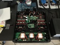
I thought I'd share my Audio-GD Master 7 (PCM1704UK DACs) modification of replacing the internal DSP1 board with Ian's SPDIF > FIFO > ISOLATOR > DUAL XO > I2StoPCM chain.
I had previously found and measured a number of issues (distortion, phase shifts between channels) with the Audio-GD USB and DSP implementations in the M7. As a result, I've since replaced all of these sub-standard components with Ian's gear. I agree with Regal above that the DAC/output sections seem very robust.
Fortunately, Audio-GD's M7 DAC is modular and I was able to connect Ian's I2StoPCM board straight into the DAC and I/V output boards.
Most troublesome bit was soldering/terminating the U.FL coax's into the through-hole solder pads of the DAC boards. I am thinking of replacing this one day with a pin header and connectors. Or maybe etching my own U.FL sockets to pin header PCBs.
Overall, I believe it has improved the sound quality significantly. I'm hearing more detail and changes in tones/keys that I wasn't hearing before with my standard reference tracks.
Operationally, I'm upsampling tracks to 192 KHz in software (OS X, Audio Midi Setup application).
There is a downside - after the modification, when I measure the output analogue waveforms (test sine waves) on my DSO, I can see distortion at sample points which I suspect are R2R glitch impulses - FYI, the glitch impulses are ~200 mVpk-pk at 192 KHz sample rate. Oddly, I never noticed these in measurements before the modification. The original DAC DSP used to do 8x upsampling = ~352 KHz with 44.1 material. I'm thinking, maybe if I run the PCM1704 chips at a higher Fs the distortion may reduce - that's my hypothesis, not sure what else may be causing it if it wasn't happening before. I will try to provide some waveform screenshots later.
Next step, I'm going to get a DIYINHK USB board, so I can upsample to 384 KHz and output into Ian's chain and into the DAC chips.
Finally, just want to thank Ian for everything he's contributed to the community - the FIFO and accessories are seriously professionally designed and implemented. I trust his equipment over most 'audio products' available on the retail market.
Attachments
Last edited:
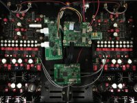
Aive nice.The Implementation is essential,you must limit the length of the cable after reclocking -between I2S to PCM board and DAC board,so that the length of cable MCKL between XO and I2S to PCM board.
With the FIFO -XO -I2Sto PCM the levels of jitter is quality,but can quickly deteriorate with poor implementation,it is useless put alot of money in a pair of very good clock if their quality is damaging by poor implementation.
Also you can adapt MMCX connectors on DAC board,and ordered UFL to MMCX cable.
img73125 partagé sur ZimageZ
I place the board like this,but it is not finished yet
img73154 partagé sur ZimageZ
With the FIFO -XO -I2Sto PCM the levels of jitter is quality,but can quickly deteriorate with poor implementation,it is useless put alot of money in a pair of very good clock if their quality is damaging by poor implementation.
Also you can adapt MMCX connectors on DAC board,and ordered UFL to MMCX cable.
An externally hosted image should be here but it was not working when we last tested it.
img73125 partagé sur ZimageZ
I place the board like this,but it is not finished yet
An externally hosted image should be here but it was not working when we last tested it.
img73154 partagé sur ZimageZ
Hey clsidxxl, great idea with those MMCX connectors. Do you have a part number for them?
1PCE MMCX Male Plug Solder RF Connector 2 54mm PCB Mount Hole Center Distance | eBay
it is necessary just file the connector for proper assembly,then scrape the varnish to bring up copper track,you can solder the ground connector,
Made sure access on the other side of the board DAC to weld properly the signal passing through of the MMCX connector.
After made you can use this eBay Boutiques |
Good luck
1PCE MMCX Male Plug Solder RF Connector 2 54mm PCB Mount Hole Center Distance | eBay
it is necessary just file the connector for proper assembly,then scrape the varnish to bring up copper track,you can solder the ground connector,
Made sure access on the other side of the board DAC to weld properly the signal passing through of the MMCX connector.
After made you can use this eBay Boutiques |
Good luck
Fantastic thanks!
Also, would you be able to take photos of connector solder onto PCB? Would like to see how you did the ground welding
if not too much trouble, thanks!
Last edited:
Is the I2S-PCM driver board usable with the AD1955 in "External Digital Filter Mode" (see AD1955 data sheet page 13).
What is called PCM there is I2S. In external filter mode however there are separate input pins for the left and right data, so that what is called here PCM.
What is called PCM there is I2S. In external filter mode however there are separate input pins for the left and right data, so that what is called here PCM.
Hello Ian,
I have the FIFOII then the Clock II then I2S to PCM board
I know I can feed the Clock II from the The FIFO II, but is it possible to feed the I2S to PCM from the FIFO II (while feeding the clock II as well) or from the Clock II with the standalone 5 V which feed the FIFO II (I have a 1 A max low noise reg).
best regards
Eldam
Hi Eldam,
Typically one would use FIFO > ISOLATOR > XO (Clock) > I2S to PCM.
The isolator is a key part of the system.. ..
The Isolator has two halves to it, the first (input side) can be fed from the FIFO power supply, the second (output side) should be fed from the XO power supply, which may or may not include the PCM board supply - but the distinction (agrh!! v2.abc) is that the supplies either side of the Isolator should be separate = isolated.
You would really want to use a separate power supply for the XO and PCM boards, (separate from the FIFO power supply) - with the Isolator sharing both supplies wrt input and outputs (PSU) as indicated above.
Hope this helps,
LH/S
Last edited:
Just an update - seemed to have fixed my CLK signal noise interference on DAC output by properly terminating PCM signals at DAC board. Yeh, don't just solder signal coax conductor into end point termination... lesson learnt.
Made a u.fl connector board with a pin header out of veroboard. Then soldered pin header straight into through hole pads on DAC board.

Made a u.fl connector board with a pin header out of veroboard. Then soldered pin header straight into through hole pads on DAC board.
- Home
- Source & Line
- Digital Line Level
- Drive NOS AD1865/62,PCM1704/02/63,TDA1541 from FIFO: Universal I2S-PCM driver board