Hi merlin el mago,
I made a full set of cables for you. Both u.fl and ph2.0 are included. Together with the u.fl sockets and some heat shrinks, they were shipped this evening in an envelope . You will receive in a week. Hope they work for you.
Regards,
Ian
Thanks Ian, I will let you know when I got it.
Cheers
Felipe
So all three leds from the converter are lit up or just the power? No, only lits the power LED
I suppose you:
- checked -without powering the units- that everything is connected and nothing shorts to ground Yes
- measured with your scope that you get the correct frequencies at each and every MCLK/SCK/CLK/WS/LLLR input and output pins I will do today
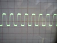
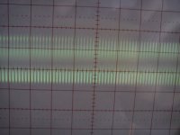
The U.FL with MCLK was not connected now LEDAUX LED is lit togheter the PWR LED, still I2S LED don't lit, attached pic with WS, SCK & MCLK arriving to the Driver NOS, obviously I can't measure nothing at LLLR & CLK Driver NOS output.
Attachments

No good luck for cataluna today (;-)
Jean-Louis
Paris
Jean-Louis, no good luck for France today(;-)
Felipe
Catalunya
Turned off and powered on LEDAUX now don't lit
Meaning of LEDs indicators on the daughter board :
No PWR: power fail
No LEDAUX with PWR: MCLK problem
No I2S with PWR and LEDAUX: I2S is wrong
Hope you can address the problem
Regards,
Ian
Real waveforms driving PCM1704 at 96 KHz and 192 KHz
I’m trying to replay the real case of merlin el mago on the last daughter board I keep.
Jumper settings: J24bit and JTAIL closed, all others open
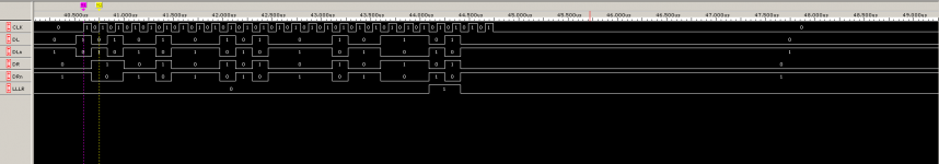
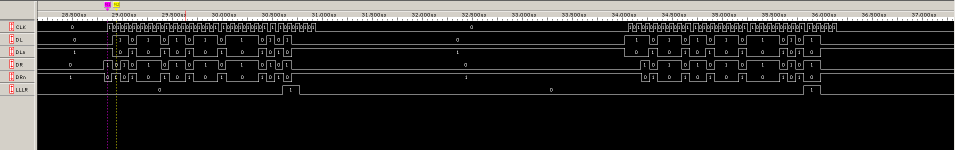
MCLK was fixed at 24.576MHz
24 bit I2S generator was running at 96 KHz and 192 KHz
The screen shot was captured from my logic analyzer. Unfortunately I don’t have a PCM1794 DAC.
Loop test confirmed bit perfect.
Maximal Fs was tested at 384 KHz, but MCLK has to be 49.152MHz or 98.304MHz with this frequency.
It seems OK from the waveform. Please let me know if you can find any problem.
Regards,
Ian
I’m trying to replay the real case of merlin el mago on the last daughter board I keep.
Jumper settings: J24bit and JTAIL closed, all others open
MCLK was fixed at 24.576MHz
24 bit I2S generator was running at 96 KHz and 192 KHz
The screen shot was captured from my logic analyzer. Unfortunately I don’t have a PCM1794 DAC
.Loop test confirmed bit perfect.
Maximal Fs was tested at 384 KHz, but MCLK has to be 49.152MHz or 98.304MHz with this frequency.
It seems OK from the waveform. Please let me know if you can find any problem.
Regards,
Ian
Attachments
Waveforms seems OK from both format and timing point of view....
It seems OK from the waveform. Please let me know if you can find any problem...
As far as clock modes are concerned I would recommend everyone to start with JCONT closed -continuous clock operation- . Only if this works try with JCONT open -stopped clock operation-
Regards,
Zsolt
p.s. I got my Amanero board and 45.xx/49.xx MHz clocks so I plan to try in 1-2 weeks the 8x mode
...too sad I missed a PCM1704 eval board on swap-meet
Last edited:
Meaning of LEDs indicators on the daughter board :
No PWR: power fail
No LEDAUX with PWR: MCLK problem
No I2S with PWR and LEDAUX: I2S is wrong
Hope you can address the problem
Regards,
Ian
Addressed the problem
I reversed the Power with the MCLK at the WaveIO  now I have signal: tested with DVM AC, now is time to listening and to test if can play 192KHz.
Greetings
Felipe
If it still doesn't play 192K nicely try to power WaveIO from a separate 5V PSU instead of USB power.
Crossing my fingers
If not operate 192K I will try the separate 5V PSU and if not operate I have the Amanero USB-I2S....
Thanks for support Zsolt.

- Home
- Source & Line
- Digital Line Level
- Drive NOS AD1865/62,PCM1704/02/63,TDA1541 from FIFO: Universal I2S-PCM driver board