2. Please read/ask about WaveIO but I suppose at V+ pin you have to input some voltage for that part of the isolator - check this
That's correct. Ask Ian to confirm what is voltage tolerance of i2s input on this pcb, do not exceed that voltage on the V+ pin on the isolated output of WaveIO.
That's correct. Ask Ian to confirm what is voltage tolerance of i2s input on this pcb, do not exceed that voltage on the V+ pin on the isolated output of WaveIO.
The input level of the daughter board is 3.3V LVTTL, but can tolerance with 5V TTL logic.
Ian
Changed the I2S cables between WaveIO & Driver NOS = no soundIsolated I2S WaveIO output have to be powered by the unused output pins?
Isolated waveio output is powered from V+ on the waveio's J6 header - see http://www.luckit.biz/downloads/WaveIO Infos.pdf
Changed the I2S cables between WaveIO & Driver NOS = no sound
- Check/ask in WaveIO thread or the seller.
- The isolator seems to be an IL715 - check where the out side VDD2 (pin16) goes...
@Ian
To make merlin el mago's life easy it would be nice he could use u-fl inputs for his converter board.
If he unsolders the 7pin PH2.0 can he put 3 u-fl on the PH2.0 pads?
According to u-fl and PH2.0 distances this should be doable - and I'm almost sure I saw maybe a dual clock-board where either you or somebody else did this.
So it needs to be powered, right?
hochopeper link says "The NVE's IL715 isolator accept 5Vdc or 3.3Vdc power supply on the V+ pin to work accordingly (please see the bottom of the card)." "Attention: There will be NO signals at J5 pin-header connector (Isolated I2S Outputs) if there's no voltage applied on the V+ and Isolated-GND pins (usually 3.3V but 5V is also accepted - please see IL715 datasheet for more information)."
TIA
Felipe
Right - either 3.3V or 5V.
Last note in the manual is also interesting:
"And, as a last note, just make sure that your WaveI
O is powered properly using a 5Vdc PSU
sourcing more than 0.5A. If you'll use the USB port
s then it's possible that some
laptop/motherboard USB power chips don't supply the
required amount of current (specified in
USB specs.) but a little bit less, making WaveIO ca
rd not to work as expected especially at
higher sample rates. "
You should better power your WaveIO with local 5V supply - if so don't forget to move J12 to EXT
...but first try to make the whole setup workable as is.
Last edited:
OK... I've found it...
If you have 3 u-fl sockets (+1 spare ) and enough (uncut) cables this is the best for your converter input: u-fl instead of PH2.0
If you do this you can forget the isolated output altogether.
... you owe me a beer
If you have 3 u-fl sockets (+1 spare
) and enough (uncut) cables this is the best for your converter input: u-fl instead of PH2.0If you do this you can forget the isolated output altogether.
... you owe me a beer
Last edited:
Today I received answer to my email sent to Lucian yesterday:
"Hello Felipe!
Here they are:
1. at V+ you will have to connect the positive side of any external PSU
that can provide 3.3V OR 5V (depending on what voltage thresholds your
DAC chip will accept!)
2. All the "Isol.GND" pins are used for grounding thus (at least one)
must be connected to the "minus" side of the PSU listed above.
Please note that the "Isol.GND" is NOT directly connected to the
WaveIO's GND thus make sure that you will keep these planes apart!
Moreover, the V+ is an INPUT pin and not one that will source anything
on it! Given this, if the power is absent there will be NO I2S signals
for you to use. In addition, place the PSU as close as possible to the
J6 header to minimize the parasitic effects.
3. "LR" stands for Left/Right signal. Basically is the Word clock in
the I2S stream.
4. "BC" is Bit Clock for I2S protocol.
5. "MC" is Master clock in case that is needed! Master Clock will always
put 22.5792 MHz or 24.576 MHz, depending on the sample rate of incoming
streams over USB.
6. "DT" is obviously, the I2S DATA pin.
As a last note, please remember that all the pins, except those one used
for power supply are OUTPUTS only.
I hope it helps,"
I understand that I have to use +5VDC to power the isolated I2S output because PCM1704 is +-5VDC powered, right?
Awesome!
merlin el mago,
Do you need single ended U.FL cables to improve signal quality? I can send you some.
Another thing is, all output signals of the daughter board work at 3.3V LVTTL logic level, I'm concerned about if your DAC can tolerance with this logic level when CLK frequency goes higher.
Regards,
Ian
Ian I need U.FL sockets to install at the I2S input & output of your Driver NOS also will be nice if you provide more uncut & cut U.FL cables to connect WaveIO to Driver NOS.
TIA
Felipe
Last edited:
...
I understand that I have to use +5VDC to power the isolated I2S output because PCM1704 is +-5VDC powered, right?
He talks about DAC chip threshold = the input voltage tolerance of the DAC and _not_ about DAC power voltages.
Since you put Ian's converter board between WaveIO and PCM1704 board you are interested in the converter board's input tolerance.
Ian said that it accepts both 3.3V or 5V.
So you can power that pin with either 3.3V or 5V - what you have at hand - both will work.
I understand that I have to use +5VDC to power the isolated I2S output because PCM1704 is +-5VDC powered, right?
In this case, the isolated i2s is going to Ian's converter and he's advised that those pins are 5V tolerant.
Ian I need U.FL sockets to install at the I2S input & output of your Driver NOS also will be nice if you provide more uncut & cut U.FL cables to connect WaveIO to Driver NOS.
TIA
Felipe
Sure, will send them to you in a letter this evening.
Ian
Sure, will send them to you in a letter this evening.
Ian
Thanks Ian.
Thanks guys, I will wait if Ian can supply U.FL (pcb sockets, cut and uncut cables).
Cheers
Felipe
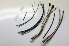
Hi merlin el mago,
I made a full set of cables for you. Both u.fl and ph2.0 are included. Together with the u.fl sockets and some heat shrinks, they were shipped this evening in an envelope . You will receive in a week. Hope they work for you.
Regards,
Ian
Attachments
So all three leds from the converter are lit up or just the power?I powered the isolated I2S WaveIO with +3.3VDC, Driver NOS LED power lits but no sound not so at least PCM 44,1KHz
I suppose you:
- checked -without powering the units- that everything is connected and nothing shorts to ground
- measured with your scope that you get the correct frequencies at each and every MCLK/SCK/CLK/WS/LLLR input and output pins
- Home
- Source & Line
- Digital Line Level
- Drive NOS AD1865/62,PCM1704/02/63,TDA1541 from FIFO: Universal I2S-PCM driver board