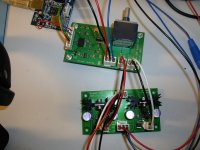
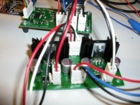
Nice simple design, and neat layout (though there is a lot of spare space)
Thanks.
IC1
http://cds.linear.com/docs/Datasheet/1763fg.pdf
Main supply in regulator.
One comment on using VEE etc for supply names, its better to use explicit voltages, it makes the schematic much easier to read and use for fault finding layout etc.
For your info is part of a guide to doing Schematics that I have done, this is art of the chapter covering net naming conventions. These naming conventions are used to specify signal and what they are explicitly to other users of circuit diagrams namely PCB design, Test and fault finding. We often get schematics with thousands of connections and nets, that have to be laid out correctly, using these naming conventions and other facilities within your CAD system (different connection codes, for ground signal, power etc, attributes or editable properties), even simple designs can benefit as it helps get things right, and improve the communication of data. There is also an IPC specification finally for schematics (IPC-2612-A), that is worth following especially if you are doing commercial work (and DIY or Hobby), the problem is you have to purchase that.
Attachments
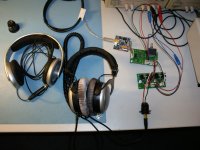
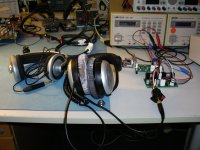
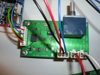
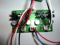
Some pictures.
The wiring is not up to my usual standards but for testing it is ok.
The wiring is not up to my usual standards but for testing it is ok.
Attachments
Last edited:
Looks nice, I would like to see how small it could be layed out for fun sometime with your permission Neutrality.
Fine by me. Besides, there is nothing special in my implementation of this DAC chip so you do not really need my permission.
I could have made it smaller if I wanted to but since I made this for my own use and it fits the cabinet I have chosen for my DAC+headphone amplifier I did not see a need.
Get rid of the pot and move some components closer and it could easily fit on a board less than 50 x 50 mm, maybe even 40 x 40 mm if you use smaller connectors, instead of the current 90 x 50 mm.
Last edited:
I have a small stack of PCBs available.
But I do not really have a BOM or to be more precise I know the sizes(housing) and values of the components used but I do not have a complete BOM with part numbers available.
So anyone buying PCBs would have to do some work on their own.
But in general, use metalfilm resistors - 5% is more than good enough, X5R/X7R ceramic capacitors, except the output filter where I used PPS film capacitors.
I am thinking about making a simple add on USB module based on PCM2707C.
It would be limited to 16 bit/48 kHz but to be honest, I do not have anything above 16 bit/44.1 kHz and I really do not expect to get any material with higher bit and sample rates than that in the near future. I basically only listen to my CD collection ripped and compressed in FLAC.
It would connect directly to the I2S input male header on the DAC board through a female header mounted on the bottom of the USB to I2S board.
Amanero, 2707 is more than just limited in speed, its just flat out limited full-stop and a big part of why USB audio initially had a bad name
You are probably right.
I am most likely going with the Amanero board, it is just too great a value.
indeed cant argue with the price that we managed to secure here with the GB, not a bad little board either. it does need a bit more filtering for the PSU (or replace it entirely since it has that option) otherwise it can let some noise through on the USB lines.
check out glt's blog, some of the execution is a bit rough, but there is some good commentary there on the amanero board and USB audio in general
check out glt's blog, some of the execution is a bit rough, but there is some good commentary there on the amanero board and USB audio in general
Neutrality,
I am interested in the final design you created for a custom multi-DAC project I have in mind for the ES9023 DACs. Can you post your final schematic?
Larry
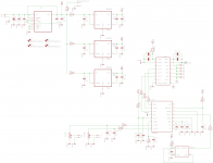
This is the final schematic.
I did not use the potentiometer in the schematic.
Attachments
- Status
- This old topic is closed. If you want to reopen this topic, contact a moderator using the "Report Post" button.
- Home
- Source & Line
- Digital Line Level
- Bragi, an Asynchronous ES9023 DAC with isolated I2S Input and Alps RK27 Volume pot