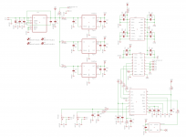
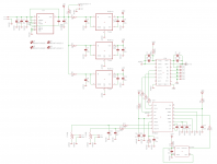
A simple board based on the ES9023 DAC running asynchronously with an 50 MHz oscillator
It has isolated I2S inputs, Analog volume control with Alps RK27 Pot.
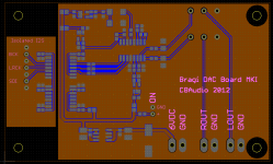
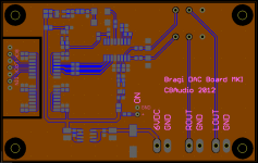
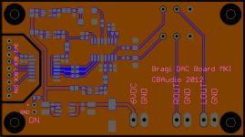
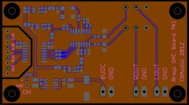
Bottom layer is a dedicated ground plane with no interruptions.
Should be supplied with 6 VDC, which is regulated down to 5 VDC by LT1763 for use with the ADuM5000 isolated DC-DC Converter powering the isolated I2S inputs and going to the 3 separate 3.3 VDC LT1761 regulators used for powering the ES9023 IC, ADuM3440 digital isolator and the 50 MHz oscillator.
It has isolated I2S inputs, Analog volume control with Alps RK27 Pot.
Bottom layer is a dedicated ground plane with no interruptions.
Should be supplied with 6 VDC, which is regulated down to 5 VDC by LT1763 for use with the ADuM5000 isolated DC-DC Converter powering the isolated I2S inputs and going to the 3 separate 3.3 VDC LT1761 regulators used for powering the ES9023 IC, ADuM3440 digital isolator and the 50 MHz oscillator.
Attachments
Last edited:
Hi the more ES9023 DACs the merrier. I think it will perform better without the RK27 though (or add a simple buffer after it). Please add a bead to the power supply pin of ES9023 too and feed it 3.6 V.
Interesting that you use 10 µF for the charge pump circuit. Did you already build it ?
Interesting that you use 10 µF for the charge pump circuit. Did you already build it ?
Last edited:
Hi the more ES9023 DACs the merrier. I think it will perform better without the RK27 though (or add a simple buffer after it). Please add a bead to the power supply pin of ES9023 too and feed it 3.6 V.
Interesting that you use 10 µF for the charge pump circuit. Did you already build it ?
ES9023 should have no problem with a 20K pot. Adding a ferrite bead to the ES9023 supply is a good idea. 3.6V just gives 2Vrms out instead of 1.9Vrms, no big difference.
Havent built it yet, just designing.
The 10uF between Cn and Cp is not a value that I have fully decided on, it could be lower than that and probably should be.
Just try the 3.6 V. You will like it better. The reason for this is not 1.9 versus 2 V.
About the RK27: the ES9023 has no problem with it but you will have a higher output impedance at normal volume. In practice it will be better to use the potentiometer at the receiving end. I have doubts if the RK27 is good enough for this application. My guess is that the DAC will sound better without it but that is easy to try out.
About the RK27: the ES9023 has no problem with it but you will have a higher output impedance at normal volume. In practice it will be better to use the potentiometer at the receiving end. I have doubts if the RK27 is good enough for this application. My guess is that the DAC will sound better without it but that is easy to try out.
Last edited:
A simple board based on the ES9023 DAC running asynchronously with an 50 MHz oscillator
It has isolated I2S inputs, Analog volume control with Alps RK27 Pot.
Bottom layer is a dedicated ground plane with no interruptions.
Should be supplied with 6 VDC, which is regulated down to 5 VDC by LT1763 for use with the ADuM5000 isolated DC-DC Converter powering the isolated I2S inputs and going to the 3 separate 3.3 VDC LT1761 regulators used for powering the ES9023 IC, ADuM3440 digital isolator and the 50 MHz oscillator.
Hi,
What is IC6 and IC7 ?
Hi,
What is IC6 and IC7 ?
IC6 is ADuM3440 digital isolator, isolates the I2S inputs.
IC7 is ADuM5000 isolated DC-DC converter. Provides power to the I2S isolator on the input side.
However, Im revising the design, adding a few ferrites, tweaking the layout and part values.
Gone is IC7, it basically draws way too much current(about 33% efficiency) and according to the datasheet it could put out some nasty switching noise, which I do not want in my circuit.
So now the digital isolator has to be supplied with a separate 3V3 supply on the input side.
You might want to use a large cap for the positive supply pin of ES9023. 100 µF or more. If you are going to use connector blocks for the outputs (if only for testing) the pads for those must be moved somewhat to the left or you will have to mount the PCB with only 3 screws ")
Last edited:
. If you are going to use connector blocks for the outputs (if only for testing) the pads for those must be moved somewhat to the left or you will have to mount the PCB with only 3 screws
There is enough room for the connector blocks, no worries, done many boards before and I know what I am doing.
This is the final schematic and layout that was sent to the manufacturer.
Overall, I must say that I am more than satisfied with how it ended up.
Took good care in ensuring an uninterrupted groundplane, good bypassing, decoupling with resistors and ferrites in appropiate places, input connector with 5 ground pins to ensure proper ground connection between source and DAC.
Overall, I must say that I am more than satisfied with how it ended up.
Took good care in ensuring an uninterrupted groundplane, good bypassing, decoupling with resistors and ferrites in appropiate places, input connector with 5 ground pins to ensure proper ground connection between source and DAC.
Attachments
Last edited:
I am almost done assembling the board.
Just need to mount the ES9023 chip, connectors and the volume pot. The volume pot I already have, the ES9023 chip and connectors I will receive on Monday.
It will go together with this : http://www.diyaudio.com/forums/headphone-systems/222369-balder-opa2134-buf634-headphone-amplifier.html
Once I get a supply board done it should fit nicely into a not too large cabinet.
Last edited:
Got it up and running.
Sent a 1kHz sine wave from my PC, through the TE7022 USB to I2S converter and then into the DAC board.
Output from the DAC board? A perfect 1kHz sine wave......
No listening impressions yet since I had no amplifier available at work but I should be getting around to listening to it sometime this week.
Anyway, I am happy that it works.
Pics might be incoming tomorrow.
Last edited:
Hi, are you still taking orders for the PCB?
Well, I have not taken any orders since I just made this for my own personal use and there has not been any interest so far.
However, I do have a few left if there is any interest.
Sorry for some reason I thought you were taking orders. I must have mixed the threads. If those you have left are based on the final design, I would like to purchase a pair. I could pay by PayPal. Let me know please. thanks
I hope you can wait a week or so, just until I actually get to do some listening tests.
I hope you can wait a week or so, just until I actually get to do some listening tests.
of course, no problem at all.
Crossposting from another thread. :
Got it(Balder) up and running today together with my ES9023 DAC(Bragi).
First impressions are very positive.
Detailed without being bright and plenty of control and power.
Tomorrow I will try it with a pair of cheap Sennheiser HD415 110dB/32 Ohm headphones as well as my "highendish" 96dB/250 Ohm Beyerdynamic DT 880 Pro headphones.
So basically I sound like everything is working as intended.
- Status
- This old topic is closed. If you want to reopen this topic, contact a moderator using the "Report Post" button.
- Home
- Source & Line
- Digital Line Level
- Bragi, an Asynchronous ES9023 DAC with isolated I2S Input and Alps RK27 Volume pot