UAE23 MODS Guide {proposed}
If you want to keep going and add more regulators, I suggest getting a mental picture of a few ways to do that.
See this thread:
http://www.diyaudio.com/forums/digi...-isolated-i2s-input-alps-rk27-volume-pot.html
look at post #12.
Christian is using regulators you could not possibly DIY solder to the UAE23, but this schematic gives an idea what to try and accomplish. DO you keep this a USB powered device? If so, then you omit the 5V regulator and add your regulators to the 5V coming in via USB. 3.6V for DAC, 3.3V for 12Mhz TCXO, 3.3V for optional 50Mhz oscillator, and the TE7022 would use the LT1763? 3.3V already on the UAE23 DAC board. An SMD proto-PCB would make it easier yet. An alternative would be: MIC5209-3.6YS looks like a good 3.6V for the DAC Digikey # 576-2371-ND $2.02USD MIC5209-3.3YS for 3.3V Digikey# 576-3516-5-ND MIC5209 family DATASHEET:
http://www.micrel.com/_PDF/mic5209.pdf
would be good for the 2 oscillators I plan on ending up with. 12Mhz Fox 924B and 50Mhz for ES9023 MCK instead of MCK signal from TE7022. I am going to try a ~$1.51 USD Fox. Digikey 631-1166-1-ND. Clocks would have to have VERY short leads on the clock pins [mount on the UAE23 board somewhere upside down]. Some people feed V+ to clocks through a ferrite bead.
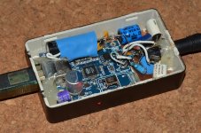
I mounted a UAE23 in a metal box and brought out audio to gold-plated RCAs. The right box would have room for a small multi-regulator SMD proto board. Or DIY regulator PCB. Chassis-mounted USB jacks can be had
http://www.parts-express.com/pe/showdetl.cfm?partnumber=092-278
In some ways the UAE23+ would be more productive to mod, but I already have external fiber-optic isolators {Opticis m2-100-03}.
If you want to keep going and add more regulators, I suggest getting a mental picture of a few ways to do that.
See this thread:
http://www.diyaudio.com/forums/digi...-isolated-i2s-input-alps-rk27-volume-pot.html
look at post #12.
Christian is using regulators you could not possibly DIY solder to the UAE23, but this schematic gives an idea what to try and accomplish. DO you keep this a USB powered device? If so, then you omit the 5V regulator and add your regulators to the 5V coming in via USB. 3.6V for DAC, 3.3V for 12Mhz TCXO, 3.3V for optional 50Mhz oscillator, and the TE7022 would use the LT1763? 3.3V already on the UAE23 DAC board. An SMD proto-PCB would make it easier yet. An alternative would be: MIC5209-3.6YS looks like a good 3.6V for the DAC Digikey # 576-2371-ND $2.02USD MIC5209-3.3YS for 3.3V Digikey# 576-3516-5-ND MIC5209 family DATASHEET:
http://www.micrel.com/_PDF/mic5209.pdf
would be good for the 2 oscillators I plan on ending up with. 12Mhz Fox 924B and 50Mhz for ES9023 MCK instead of MCK signal from TE7022. I am going to try a ~$1.51 USD Fox. Digikey 631-1166-1-ND. Clocks would have to have VERY short leads on the clock pins [mount on the UAE23 board somewhere upside down]. Some people feed V+ to clocks through a ferrite bead.
I mounted a UAE23 in a metal box and brought out audio to gold-plated RCAs. The right box would have room for a small multi-regulator SMD proto board. Or DIY regulator PCB. Chassis-mounted USB jacks can be had
http://www.parts-express.com/pe/showdetl.cfm?partnumber=092-278
In some ways the UAE23+ would be more productive to mod, but I already have external fiber-optic isolators {Opticis m2-100-03}.
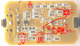
Many thanks to enjoybiking for the suggested mods. I've outlined a few of them directly in the attached PCB photo (I have yet to implement these changes in my UAE23).
In the first phase I will try to do Ua, Ra, Ca, Cf, Cg, and the X cut.
Ua=MIC5209-3.6BS (separate 3.6V reg for the ES9023; upside down)
Ra=100k (similar to the ODAC)
Ca=10u+2.2u (alternatively, replace C9 by 22u and add 100n here)
Cf=22u (see reference Ua design)
Cg=0.1u (see reference Ua design)
In the second phase I'm thinking of adding the other caps and replacing Y1 by Ya, and maybe add some ferrites.
If anyone has any other suggestions or advice about the mods, please let me know. It would be great if someone could help do proper measurements before and after the mods. The whole idea is about pushing this DAC from being good to great for a little premium (say $10-15; labour, tools, and shipping excluded).
DISCLAIMER: All the above mods are strictly DIY mods and are all at your own risk and will void any warranty there may be.
Attachments
UAE23 mods...
...and for what it is worth I am just a long-time hobbyist, certainly not a DAC engineer, and have recently been dragging myself into the SMD world. Also, what I do to a little DAC like this that is already made is not always the same thing as what I wish-I-could-do, or I try something and like it so I stop instead of getting more scientific. Some might have a ferrite on the V+ to the clock, or some R between the TCXO out and the XI pin of the TE7022 {33 ohms let's say}. But, I didn't have one {or I do, but WHERE?} and after doing surgery on the DAC, of course wanted to hear the patient lived. {good to take a listen between stages of modification!!}
SO far I have been guided by some wizards way beyond my abilities -- soldering techniques and what tools and supplies to have around, what Youtube videos to watch on SMD soldering... and I appreciate the nudge to "just DO it".
As to component values, yikes, I have looked at maybe ~7x ES9023 schematics now, each person having their own opinion, either closely based on the somewhat lacking ESS tech PDF or... opinion, or testing. Much has been shared by the ODAC project {for instance}, and those people tested what they chose more scientifically than I ever will. One thing I got from my reading is that when it comes to caps, the kind and values... too much at the wrong place can degrade the circuit. {for instance the charge-pump} Certainly I have tried a few things that didn't work well, and I have not trashed anything YET. When picking say a new regulator to try, I will look at the datasheet and suggested implementation {caps etc surrounding it}, and I think about what is already in the device being modded.
Modded two UAE23 so far, the second one with much less haste and with some rethinking about where to put new components [shorter clock leads etc}. Lots of fun and they did sound nicer. Meanwhile better parts are showing up at my door, like ferrite beads and the SOT-223 sized Micrel regulators, SMD fanout boards...
I'd also like to point out that a stock UAE23 is a great buy and can blow away some DAC hardware I used to think was special. Without our friends at HifimeDIY we would not be having so much fun! I think the UAE23+ has even more potential {for home stereo not portable headphone use}, and a nice metal box with more room to play.
Many thanks to enjoybiking for the suggested mods. I've outlined a few of them directly in the attached PCB photo (I have yet to implement these changes in my UAE23).
...and for what it is worth I am just a long-time hobbyist, certainly not a DAC engineer, and have recently been dragging myself into the SMD world. Also, what I do to a little DAC like this that is already made is not always the same thing as what I wish-I-could-do, or I try something and like it so I stop instead of getting more scientific. Some might have a ferrite on the V+ to the clock, or some R between the TCXO out and the XI pin of the TE7022 {33 ohms let's say}. But, I didn't have one {or I do, but WHERE?} and after doing surgery on the DAC, of course wanted to hear the patient lived. {good to take a listen between stages of modification!!}
SO far I have been guided by some wizards way beyond my abilities -- soldering techniques and what tools and supplies to have around, what Youtube videos to watch on SMD soldering... and I appreciate the nudge to "just DO it".
As to component values, yikes, I have looked at maybe ~7x ES9023 schematics now, each person having their own opinion, either closely based on the somewhat lacking ESS tech PDF or... opinion, or testing. Much has been shared by the ODAC project {for instance}, and those people tested what they chose more scientifically than I ever will. One thing I got from my reading is that when it comes to caps, the kind and values... too much at the wrong place can degrade the circuit. {for instance the charge-pump} Certainly I have tried a few things that didn't work well, and I have not trashed anything YET. When picking say a new regulator to try, I will look at the datasheet and suggested implementation {caps etc surrounding it}, and I think about what is already in the device being modded.
Modded two UAE23 so far, the second one with much less haste and with some rethinking about where to put new components [shorter clock leads etc}. Lots of fun and they did sound nicer. Meanwhile better parts are showing up at my door, like ferrite beads and the SOT-223 sized Micrel regulators, SMD fanout boards...
I'd also like to point out that a stock UAE23 is a great buy and can blow away some DAC hardware I used to think was special. Without our friends at HifimeDIY we would not be having so much fun! I think the UAE23+ has even more potential {for home stereo not portable headphone use}, and a nice metal box with more room to play.
One thing I got from my reading is that when it comes to caps, the kind and values... too much at the wrong place can degrade the circuit. {for instance the charge-pump}.
Hi, what cap do people try for the charge pump and what value / type works best ? I guess film cap and 1uF ? Thank you.
UAE23 mods: the 3.6V regulator
I mounted my second regulator 90 degrees more clockwise {and yes, upside down} and tacked the regulator input to the USB 5v+ directly. It might be possible to tack a second ferrite there to the +5V "u" of trace there and feed the second regulator {mounted with feet almost straight up, maybe 10PM}.
If you wanted a third regulator, it MIGHT be possible to vertically stack TWO regulators. 3.6{DAC} and 3.3 {TCXO} SOT-223 style like you drew. Will it fit the plastic case? Maybe not.
Many thanks to enjoybiking for the suggested mods. I've outlined a few of them directly in the attached PCB photo (I have yet to implement these changes in my UAE23).
I mounted my second regulator 90 degrees more clockwise {and yes, upside down} and tacked the regulator input to the USB 5v+ directly. It might be possible to tack a second ferrite there to the +5V "u" of trace there and feed the second regulator {mounted with feet almost straight up, maybe 10PM}.
If you wanted a third regulator, it MIGHT be possible to vertically stack TWO regulators. 3.6{DAC} and 3.3 {TCXO} SOT-223 style like you drew. Will it fit the plastic case? Maybe not.
Sure, the mods' outline is just indicative. For example, there is actually more space for Cb and Ya on the other (=front) side of the PCB. The Ra could also go straight onto the R3 pads.I mounted my second regulator 90 degrees more clockwise {and yes, upside down} ...
UAE23 MODS: charge-pump
http://www.6moons.com/audioreviews/resonessence2/open_big.png
part of a review at:
6moons audio reviews: Resonessence Labs Concero
CP? Probably 1uf like the ESS tech PDF, no markings but looks small, I doubt anyone has UNDER-sized CP cap. This design seems to use 220K on ES9023 pin#6 {Where ODAC uses 118K at 3.6Vdac, and I'm liking my 100K}. Note the 1117 regulators, I am not being a regulator snob but some might... and note the use of what looks like series Rs on the outs {another place I see different opinions, for instance ODAC at 220 ohms series, and 2200pF to ground}. I cannot tell if the caps there are wired CRC like Pi
Hi, what cap do people try for the charge pump and what value / type works best ? I guess film cap and 1uF ? Thank you.
http://www.6moons.com/audioreviews/resonessence2/open_big.png
part of a review at:
6moons audio reviews: Resonessence Labs Concero
CP? Probably 1uf like the ESS tech PDF, no markings but looks small, I doubt anyone has UNDER-sized CP cap. This design seems to use 220K on ES9023 pin#6 {Where ODAC uses 118K at 3.6Vdac, and I'm liking my 100K}. Note the 1117 regulators, I am not being a regulator snob but some might... and note the use of what looks like series Rs on the outs {another place I see different opinions, for instance ODAC at 220 ohms series, and 2200pF to ground}. I cannot tell if the caps there are wired CRC like Pi
UAE23 mods: 3.6V & 50 Mhz
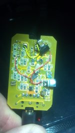
I did put a Fox XpressO 50.000 mHz clock on topside this morning, it is upside down with it's back laying on ES9023, OSC pin #3 feds the MCK pin on ES9023 with a few mm bare wire-wrap wire. OSC EN and V+ pins are towards bottom edge of board. GND from OSC to scratched clean top ground ground-plane spot {out left of DAC pins 2&3}. Once this was is place I cut trace coming from TE7022 pin#3 to the DAC, I did so where the trace heads East {flat} and cut away from myself towards the TE7022 so as not to nick the pin 2 and pin 1 TE7022 traces.
3.6V Micrel 5209 regulator is now much as you drew it on bottom of board by USB IN wires. Rather than desolder my old 3.3V TPS79633 I used it to run the new 50MHz clock, I ran the + wire up through that big hole [bottom right of your pic]. I added a decoupling cap to the OSC from EN pin to ground [EN is wire-bridged to V+ pin on 50M OSC]. I was able to use a wire-leaded cap there, typically that would be something like a 103 cap {0.01uF}. The Micrel's top TAB is stacked over the TPS79633 tab over edge of that large grounded hole. Micrel is NOT upside down.
So dedicated regulators for DAC, 50Mhz clock, and TE7022+12Mhz TCXO {sharing the onboard LT1763}.
DAC Vcc pin also gut a 22uF tiny can cap today, spanning that cap{s} aready at the DAC power injection point {below the etch cut on your drawing}
I may go back to the dungeon and try 470 ohms in series with left and right out lines before they hit the supersonic filter caps-to-ground. If I do that it will be fine knife-cuts to traces and bridge the cuts with SMD R 0603 or 0805 size.
Then to remember which side is right, and mount in box with RCAs.
{it is also possible to export/simulcast Toslink at the SAME TIME, just leave a 3.5mm Toslink cable plugged in. I have no use for it but the DAC will support it}
How does it sound? It was great before this wave, but it sure does have a nice sound-stage. The best contrast I can draw is my TE8802 + ak4396 combo: very precise but not as 3D... This is better, the best I've ever had. Sorry, no pix of Oriental rugs, wine, $30K mono-blocked stuff I don't own. I do add a touch of BBE {BBE is modded with high end CAPS in/out}. The music is in top-grade FLAC {we do not spin CDs anymore}
BBE Sound: Technologies: BBE HD Sound
and the speakers are time-aligned, Genesis Genre I {3-way}
www.[B]genesisloudspeakers[/B].com/.../genrei_ii/genre_brochure.pdf
18" 1KW Aura SUB is "off" no need.
Sure, the mods' outline is just indicative. For example, there is actually more space for Cb and Ya on the other (=front) side of the PCB. The Ra could also go straight onto the R3 pads.
I did put a Fox XpressO 50.000 mHz clock on topside this morning, it is upside down with it's back laying on ES9023, OSC pin #3 feds the MCK pin on ES9023 with a few mm bare wire-wrap wire. OSC EN and V+ pins are towards bottom edge of board. GND from OSC to scratched clean top ground ground-plane spot {out left of DAC pins 2&3}. Once this was is place I cut trace coming from TE7022 pin#3 to the DAC, I did so where the trace heads East {flat} and cut away from myself towards the TE7022 so as not to nick the pin 2 and pin 1 TE7022 traces.
3.6V Micrel 5209 regulator is now much as you drew it on bottom of board by USB IN wires. Rather than desolder my old 3.3V TPS79633 I used it to run the new 50MHz clock, I ran the + wire up through that big hole [bottom right of your pic]. I added a decoupling cap to the OSC from EN pin to ground [EN is wire-bridged to V+ pin on 50M OSC]. I was able to use a wire-leaded cap there, typically that would be something like a 103 cap {0.01uF}. The Micrel's top TAB is stacked over the TPS79633 tab over edge of that large grounded hole. Micrel is NOT upside down.
So dedicated regulators for DAC, 50Mhz clock, and TE7022+12Mhz TCXO {sharing the onboard LT1763}.
DAC Vcc pin also gut a 22uF tiny can cap today, spanning that cap{s} aready at the DAC power injection point {below the etch cut on your drawing}
I may go back to the dungeon and try 470 ohms in series with left and right out lines before they hit the supersonic filter caps-to-ground. If I do that it will be fine knife-cuts to traces and bridge the cuts with SMD R 0603 or 0805 size.
Then to remember which side is right, and mount in box with RCAs.
{it is also possible to export/simulcast Toslink at the SAME TIME, just leave a 3.5mm Toslink cable plugged in. I have no use for it but the DAC will support it}
How does it sound? It was great before this wave, but it sure does have a nice sound-stage. The best contrast I can draw is my TE8802 + ak4396 combo: very precise but not as 3D... This is better, the best I've ever had. Sorry, no pix of Oriental rugs, wine, $30K mono-blocked stuff I don't own. I do add a touch of BBE {BBE is modded with high end CAPS in/out}. The music is in top-grade FLAC {we do not spin CDs anymore}
BBE Sound: Technologies: BBE HD Sound
and the speakers are time-aligned, Genesis Genre I {3-way}
www.[B]genesisloudspeakers[/B].com/.../genrei_ii/genre_brochure.pdf
18" 1KW Aura SUB is "off" no need.
Good picture - thank you. Looks 1uF ceramic only. If this is charge pump, maybe it is noisy, so better to put 0.1uF COG on IC pins direct. Also add low esr 1uF like polyester film ? Charge pump is supply for inside op amp, so better cap maybe improve THD+N ? Anyone try ?
Good picture - thank you. Looks 1uF ceramic only. If this is charge pump, maybe it is noisy, so better to put 0.1uF COG on IC pins direct. Also add low esr 1uF like polyester film ? Charge pump is supply for inside op amp, so better cap maybe improve THD+N ? Anyone try ?
I am no expert on the ES9023 or this DAC but in my experience the DAC distorts unless the master system slider gain is down some, though that varies depending on what internal settings I use in my favorite PC player: Jriver MEdia Center. I run the DAC at 3.6V not UAE23 stock 3.3V and I use 100K on ES9026 pin 6 to ground. On the CP pins I use a small mix of SMD caps totally maybe 2-3-4uF, too much is too much. On the NEG pin we have varying opinions out on the threads, ODAC uses 22uF. When the DAC is not clipping, however you get there, it's really special. Nothing I have done to the CP pins has helped the clipping, the sliders do, the pin #6 resistor does but not yet 100% on it's own.
DIY es9023
I made this. Look bad but sound very good ! There is seperate 2 ground planes for dgnd and agnd. It use TL1963 3.3V regulator. Input to regulator through RC = 7R x 2200uF Rubycon YXG +100nF. Output 470uF BC038 + 100nF. R8 = 143K RN55 parallel to 10uF Panasonic AM-X +100nF. Neg use 22uF Nichicon FW + 100nF. CN_CP use 1uF X7R + 100nF. Mute use 100K + 5uF.No series R on analogue. Only have 4700pF Multicap PPMFX (metal polypropylene) output to agnd. Tenor use 12Mhz XO91 <1ps rms jitter. Input to Tenor through capacitance multiplier.
Sound is very good. No clipping/distortion. Very very small pop noise when plug into USB. I use Foobar, kernel streming, no driver. There is low jitter sound quality so this is very good value part.")
I made this. Look bad but sound very good ! There is seperate 2 ground planes for dgnd and agnd. It use TL1963 3.3V regulator. Input to regulator through RC = 7R x 2200uF Rubycon YXG +100nF. Output 470uF BC038 + 100nF. R8 = 143K RN55 parallel to 10uF Panasonic AM-X +100nF. Neg use 22uF Nichicon FW + 100nF. CN_CP use 1uF X7R + 100nF. Mute use 100K + 5uF.No series R on analogue. Only have 4700pF Multicap PPMFX (metal polypropylene) output to agnd. Tenor use 12Mhz XO91 <1ps rms jitter. Input to Tenor through capacitance multiplier.
Sound is very good. No clipping/distortion. Very very small pop noise when plug into USB. I use Foobar, kernel streming, no driver. There is low jitter sound quality so this is very good value part.
Attachments
Last edited:
I did some listening tests for other DACs and this. This DAC has very good vocals, and deep bass and high treble detail is good. Stereo is good but not big. All together, it does not sound better than WM8741, and sound different but not better than CS4398. But maybe it is no-pcb way I make it. I use star-earth for all agnd connection to agnd plane. LRCLK and Data are direct on pcb. BCLK and MCLK are very short wire but above pcb - not best way. Some 100nF are smd on pins - CN_CP is smd ceramic on pins, NEG is smd ceramic on pins. Other 100nF are big with wires. It is good value DAC IC but not giant killer. I can recommend it.
DIY es9023
I give up, where did you hide the DAC?
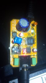
Attached are pix of my modded UAE23 I may redo parts of it, but it works well.
The top 50Mhz Oscillator I would like a better cap arrangement and maybe a ferrite bead.
I made this. Look bad but sound very good !
I give up, where did you hide the DAC?
Attached are pix of my modded UAE23 I may redo parts of it, but it works well.
The top 50Mhz Oscillator I would like a better cap arrangement and maybe a ferrite bead.
Attachments
I did some listening tests for other DACs and this. This DAC has very good vocals, and deep bass and high treble detail is good. Stereo is good but not big. All together, it does not sound better than WM8741, and sound different but not better than CS4398. But maybe it is no-pcb way I make it. I use star-earth for all agnd connection to agnd plane. LRCLK and Data are direct on pcb. BCLK and MCLK are very short wire but above pcb - not best way. Some 100nF are smd on pins - CN_CP is smd ceramic on pins, NEG is smd ceramic on pins. Other 100nF are big with wires. It is good value DAC IC but not giant killer. I can recommend it.
difference vs cs4398 ? (what use in the cs out ?)
I give up, where did you hide the DAC?
Attached are pix of my modded UAE23 I may redo parts of it, but it works well.
The top 50Mhz Oscillator I would like a better cap arrangement and maybe a ferrite bead.
DAC lives at edge of tenor pcb, and top is down, so LRCLK and Data are direct connection - pin to tenor pcb.
How is 50mhz ? better ?
CS4398 is Musiland MD10 with ad8599 op amp and good xo. Needs better power.
50Mhz better?
I like the 50Mhz Osc but what I need to DO is compare the two, the second UAE23 is at my Sister and Brother-in-law's and does NOT have the 50 OSC... I have to leave my UAE23 with them to compare. If I do more modding on these I will use a stack of 3 regulators SOT-223 {stack them, bend down the leads... fly the + outs with wirewrap wires...} it would be very neat. I think the TCXO at 12.000mHz helped, I KNOW my jump to 3.6Vdac, and 100K on pin#6 ES9023 helped. USB isolation helped {I use an OPticis m2-100-03 fiber-optic isolator, it has one sin, a switching 5V PSU at the remote end, but it seems quiet}.
I had a lesser CS4398, TE7022 combo... it was clean but this UAE23 {modded} has more soundstage, more "middle" "to me". It too had a so-so PSU arrangement. They guy I sold it to heard one of these UAE23 the other day and WANTS ONE.
DAC lives at edge of tenor pcb, and top is down, so LRCLK and Data are direct connection - pin to tenor pcb.
How is 50mhz ? better ?
CS4398 is Musiland MD10 with ad8599 op amp and good xo. Needs better power.
I like the 50Mhz Osc but what I need to DO is compare the two, the second UAE23 is at my Sister and Brother-in-law's and does NOT have the 50 OSC... I have to leave my UAE23 with them to compare. If I do more modding on these I will use a stack of 3 regulators SOT-223 {stack them, bend down the leads... fly the + outs with wirewrap wires...} it would be very neat. I think the TCXO at 12.000mHz helped, I KNOW my jump to 3.6Vdac, and 100K on pin#6 ES9023 helped. USB isolation helped {I use an OPticis m2-100-03 fiber-optic isolator, it has one sin, a switching 5V PSU at the remote end, but it seems quiet}.
I had a lesser CS4398, TE7022 combo... it was clean but this UAE23 {modded} has more soundstage, more "middle" "to me". It too had a so-so PSU arrangement. They guy I sold it to heard one of these UAE23 the other day and WANTS ONE.
Isolation
I am sorry isolation didn't work well for you -- I have given the fiber isolators to family members and everyone could hear the improvement [so far just on TE7022 receivers]. Beyond 24/96 USB isolation at 480 would be expensive -- progressing into that world I see I2S isolation {instead, or, not at all}. The best way I can describe USB isolation is this. I live in a city, when I go outside I hear the drone of cars on bigger roads in the distance. When I am in a remote place I hear nothing. I live in a City, I ignore the noise, but when it's GONE... nicer. I wonder if anyone here has compared UAE23 to UAE23+ and how they like the isolator in the 23+ vs not? Well, there are MANY factors there, like where power is coming from.
The mods I have done I would do better a third or fourth time, maybe place ferrite bead on the V+ clock pad{s}... It would be a waste of some good parts and precious TIME, to start over from nothing, but I might try adding beads. The second time I put in a 12.000mHz clock I moved it close to the crystal pads -- YOU are wiring the DAC parts in free air? {NOT modding a UAE23} WoW!! I have a few Es9023 on SMD to DIP boards, but that usually means I2s signals have a longer path. [and probably would not fit in your little DAC box]. I am not a headphone guy so second UAE23 ended up in a black metal chassis with gold RCA jacks. [UAE23+ was just coming out when I started this tweaking, that would have been easier, I will probably buy one to keep the fun going].
I tried adum4160 usb isolater with this. It is better for mid and treble (less thd ?) but less deep for bass (more jitter ?). Less trouble without so without is my choice.
I will try 50mhz. thank you.
I am sorry isolation didn't work well for you -- I have given the fiber isolators to family members and everyone could hear the improvement [so far just on TE7022 receivers]. Beyond 24/96 USB isolation at 480 would be expensive -- progressing into that world I see I2S isolation {instead, or, not at all}. The best way I can describe USB isolation is this. I live in a city, when I go outside I hear the drone of cars on bigger roads in the distance. When I am in a remote place I hear nothing. I live in a City, I ignore the noise, but when it's GONE... nicer. I wonder if anyone here has compared UAE23 to UAE23+ and how they like the isolator in the 23+ vs not? Well, there are MANY factors there, like where power is coming from.
The mods I have done I would do better a third or fourth time, maybe place ferrite bead on the V+ clock pad{s}... It would be a waste of some good parts and precious TIME, to start over from nothing, but I might try adding beads. The second time I put in a 12.000mHz clock I moved it close to the crystal pads -- YOU are wiring the DAC parts in free air? {NOT modding a UAE23} WoW!! I have a few Es9023 on SMD to DIP boards, but that usually means I2s signals have a longer path. [and probably would not fit in your little DAC box]. I am not a headphone guy so second UAE23 ended up in a black metal chassis with gold RCA jacks. [UAE23+ was just coming out when I started this tweaking, that would have been easier, I will probably buy one to keep the fun going].
I really don't like USB isolation since you are limited to 24Bit/96kHz.
A better option is isolation of the I2S signals instead, then there is no problem at all getting higher than 24/96 from an USB connection since it is easy to get digital isolators that can handle much higher than 24/96 without a problem.
An ES9023 DAC running asynchronously with a 50.000MHz clock and isolation of the incoming BCK, LRCK, DIN signals through a digital isolator like the IL715 is an easy way to get isolation from the PC without limiting yourself to 24/96 which is what you get as a maximum with an USB isolator.
You could go a bit further and run the ES9023 synchronously. Keep the digital isolator, take the digital output from it and fed it to a AD1896 ASRC, input side as slave, output side as master with a 24.576MHz clock feeding the AD1896 as well as the ES9023. Then you will have isolation from the PC, upsampling to 96kHz and running the ES9023 Master clock synchronously with the AD1896 Master clock with the BCK, LRCK, DIN signals in perfect synch.
Last edited:
PCB
I'd need a PCB for that from some Genius guy in Denmark; I officially suck at Eagle CAD {I just need time, maybe audit a course at the University here?}.
I was thinking sooner than that I might try a CM6631 non-A because I have it, maybe into one of YOUR boards, the world Famous Bragi
http://www.diyaudio.com/forums/digi...-isolated-i2s-input-alps-rk27-volume-pot.html
I seem to be behind the times
I really don't like USB isolation since you are limited to 24Bit/96kHz.
A better option is isolation of the I2S signals instead, then there is no problem at all getting higher than 24/96 from an USB connection since it is easy to get digital isolators that can handle much higher than 24/96 without a problem.
An ES9023 DAC running asynchronously with a 50.000MHz clock and isolation of the incoming BCK, LRCK, DIN signals through a digital isolator like the IL715 is an easy way to get isolation from the PC without limiting yourself to 24/96 which is what you get as a maximum with an USB isolator.
You could go a bit further and run the ES9023 synchronously. Keep the digital isolator, take the digital output from it and fed it to a AD1896 ASRC, input side as slave, output side as master with a 24.576MHz clock feeding the AD1896 as well as the ES9023. Then you will have isolation from the PC, upsampling to 96kHz and running the ES9023 Master clock synchronously with the AD1896 Master clock with the BCK, LRCK, DIN signals in perfect synch.
I'd need a PCB for that from some Genius guy in Denmark; I officially suck at Eagle CAD {I just need time, maybe audit a course at the University here?}.
I was thinking sooner than that I might try a CM6631 non-A because I have it, maybe into one of YOUR boards, the world Famous Bragi
http://www.diyaudio.com/forums/digi...-isolated-i2s-input-alps-rk27-volume-pot.html
I seem to be behind the times
- Status
- This old topic is closed. If you want to reopen this topic, contact a moderator using the "Report Post" button.
- Home
- Source & Line
- Digital Line Level
- Hifimediy ES9023+TE7022 24/96 USB Dac