Hi,
i have this one:
24/192 , 24/96 CM6631 USB to COAX OPT SPDIF convertor for DAC - PCM270X killer | eBay
and it doesn't work with Win7, tried with 3 different drivers, LED flashes on,
but drivers won't work...
Seller suggested to flash firmware win a Win XP computer, but as do not have one, i still have a non working CM6631
Hi,
I thought I'd add some updates about the one I've bought.
I found the ASIO driver (downloaded through the Ebay ad) only works for I2S, not spdif, and again, no 88 or 176.
I can't find a datasheet to download but v0.8 (March 2010) can be viewed here :
CM6631_Datasheet_v0.8_°Ù¶ÈÎÄ¿â
The sheet says there is 3.3V output buffer on the spdif output (pin 38, 8ma output), and there is 1.63V DC on the pin, so it seems likely the logic levels need to be attenuated for spdif ? It also says its low level output is 0.4V and high level is 2.4V = 2v range ? Does anyone's pcb have any kind of attenuation on the spdif output circuit ?
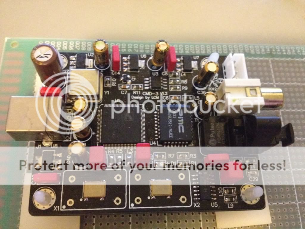
My pcb has no spdif components :
So I added a 0.1uF COG smd cap in series, then a 300R smd resistor in series and then a pulse transformer (PE65612) and 100R res in parallel. This is about 75 ohms impedance and attenuates -12dB - so the assumed 2V output range drops to 0.5 for spdif - and the load should not exceed the pin's 8mA output - and it works well it seems. I'll need to get a look on a scope at some point to be sure how well...
So next up is to desolder the usb socket and give it clean power.
cheers
I thought I'd add some updates about the one I've bought.
I found the ASIO driver (downloaded through the Ebay ad) only works for I2S, not spdif, and again, no 88 or 176.
I can't find a datasheet to download but v0.8 (March 2010) can be viewed here :
CM6631_Datasheet_v0.8_°Ù¶ÈÎÄ¿â
The sheet says there is 3.3V output buffer on the spdif output (pin 38, 8ma output), and there is 1.63V DC on the pin, so it seems likely the logic levels need to be attenuated for spdif ? It also says its low level output is 0.4V and high level is 2.4V = 2v range ? Does anyone's pcb have any kind of attenuation on the spdif output circuit ?
My pcb has no spdif components :
An externally hosted image should be here but it was not working when we last tested it.
So I added a 0.1uF COG smd cap in series, then a 300R smd resistor in series and then a pulse transformer (PE65612) and 100R res in parallel. This is about 75 ohms impedance and attenuates -12dB - so the assumed 2V output range drops to 0.5 for spdif - and the load should not exceed the pin's 8mA output - and it works well it seems. I'll need to get a look on a scope at some point to be sure how well...
An externally hosted image should be here but it was not working when we last tested it.
An externally hosted image should be here but it was not working when we last tested it.
So next up is to desolder the usb socket and give it clean power.
cheers
Last edited:
Thanks for the bigger photo. It's hard to tell if that pin 38 goes into a via or C7 ?
Here's the full underside of mine. I was relieved to see no vias on the I2S lines and a contiguous ground plane on the other side. In fact, I'm very pleased with the design of this board.

Here's the full underside of mine. I was relieved to see no vias on the I2S lines and a contiguous ground plane on the other side. In fact, I'm very pleased with the design of this board.
Last edited:
Hi,
I think I'm finished modifying this so here's a last update.
Here is the spdif circuit I'm using :

which I decided on after reading a bunch of threads, including this :
http://www.diyaudio.com/forums/digital-source/67247-s-pdif-digital-output.html
I also made a "power cleaner" from a capacitance multiplier :

R1 = 100R, R2 = 910 (total 1K so that's an extra 5mA draw on 5V input), Q = BD139 (the board draws 132mA so a BC550 wouldn't quite handle the current), and C1 = 100uF Panasonic FM.
This gives 3.6V under load for a 5V input and the LP5900 is 3.3V with 80mV dropout, and corner frequency of a few Hz for the noise filter.
I also added a Nichicon PLE 820uF ultra low esr cap, after the cap multiplier to further reduce noise on the supply.
I can definitely recommend this board - it sounds better than any other usb receiver I've tried.
cheers
I think I'm finished modifying this so here's a last update.
Here is the spdif circuit I'm using :
which I decided on after reading a bunch of threads, including this :
http://www.diyaudio.com/forums/digital-source/67247-s-pdif-digital-output.html
I also made a "power cleaner" from a capacitance multiplier :
R1 = 100R, R2 = 910 (total 1K so that's an extra 5mA draw on 5V input), Q = BD139 (the board draws 132mA so a BC550 wouldn't quite handle the current), and C1 = 100uF Panasonic FM.
This gives 3.6V under load for a 5V input and the LP5900 is 3.3V with 80mV dropout, and corner frequency of a few Hz for the noise filter.
I also added a Nichicon PLE 820uF ultra low esr cap, after the cap multiplier to further reduce noise on the supply.
I can definitely recommend this board - it sounds better than any other usb receiver I've tried.
cheers
I'm very pleased with the design of this board.
An externally hosted image should be here but it was not working when we last tested it.
Hi, I saw on ebay this board that costs the same price like yours (29 $) but it is a more complex design having optical and coax outputs (with isolation transformer included) already mounted and also an extra power input switch for clean external power supply option; so what is that more preciselly on which you are so pleased with the design of your own board, what technical advantage does it have over this newest design?
CM6631 USB DAC Coaxial Fiber 192kHz 32bit I2S 192K 24bit SPDIF WLX 66 | eBay
You can read this and find the different
TI USB 2.0 Board Design and Layout Guidelines
http://www.ti.com/lit/an/spraar7/spraar7.pdf
but if people only like eye catching big size capacitor, it's easy to choice
Hi, I saw on ebay this board that costs the same price like yours (29 $) but it is a more complex design having optical and coax outputs (with isolation transformer included) already mounted and also an extra power input switch for clean external power supply option; so what is that more preciselly on which you are so pleased with the design of your own board, what technical advantage does it have over this newest design?
CM6631 USB DAC Coaxial Fiber 192kHz 32bit I2S 192K 24bit SPDIF WLX 66 | eBay
Hi,
I'd need a better photo than the one posted on Ebay to be certain, and definitely a photo of the underside, but it seems the component placement and routing on that board will not maintain signal integrity as well as the one I bought, however, it does seem to be pretty decent; perhaps the phase noise of the clocks and the noise of the regulators would be more critical.
Also - what reg does that one use ? The one I have uses an ultra low noise reg - LP5900. (EDIT Zoe Tsang text says AMS1117 - horribly noisy reg - definitely a strong disadvantage)
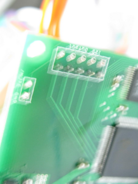
For example of a small improvement in layout, on the one I got, look at the signal lines from the clocks into the CM. That shows the designer knows how critical the signal on those lines is, so they are very short and unbroken with no vias, etc.
Unfortunately, they are both 2-layer boards but at least I know the one I got has a contigous ground plane on one side, so there is a ground return for all the lines, and none go through vias (holes to the underside), and none cross other lines of any kind. There are kinks in the lines but not a lot of them; so all in all, that's about as good as it gets for signal integrity. There's only one downside - the I2S output should really be available as GSGSGSGSG (g=ground s=signal) but as you can see on mine it is GSSSS. Also, I would expect to see some small smd resistors on the output (tx) to damp reflections from the receiver (rx)
There are lots of threads about this on this site. I'm no expert. I only finished one year of EE at uni, and I've forgotten most of that. But I'm a good learner, and a lot of it is common sense once you get the fundamentals about impedance at high frequency, ground returns, reflections, jitter, etc.
Most people want the best possible square wave signal because this produces the best possible sound, so noise levels and signal integrity are the most important things.
Hope this helps.
Last edited:
 Klipschkid, please read this thread an consider it when posting your photos with giant files sizes.
http://www.diyaudio.com/forums/everything-else/183084-pictures-why-not-attach-them.html
Thank you.
Seller has asked me to delete the image of the underside of his board; so if they are missing above, you know why. I have deleted it from Flickr. Sorry. I suggest you contact the seller if you want to see it. There's so much copying in this part of the world, it's a perfectly reasonable request.
Pano - is this a browser problem ? The images resize automatically on every PC I use. What exactly is the issue ? Anyway, feel free to delete post 45 and any offending pictures. Please accept my apologies.
Pano - is this a browser problem ? The images resize automatically on every PC I use. What exactly is the issue ? Anyway, feel free to delete post 45 and any offending pictures. Please accept my apologies.
Last edited:
thanks for your answers, although I must say that I find it a little bit strange that all of you who replied in favor for that design are from the same country as the ebay seller of this design, having the HK flag beside your usernames...maybe coincidence
this pcb ship from HK, local people should received it faster
our lastest well known design is ddc pump pcb in the water cooling world,
many diyer are happy with it's performance, google is good source for it.
negative comment is also welcome to improve this pcb
thanks for your clarification, I saw that you provide also a board which has optical output already mounted, so my question is if you could provide a board with coax SPDIF output mounted instead of optical (with or without isolation transformer), since coaxial electrical output is well known in the audiophille world to sound much better than optical, thus many buyers would be searching for such a design instead of optical output.
thanks for your clarification, I saw that you provide also a board which has optical output already mounted, so my question is if you could provide a board with coax SPDIF output mounted instead of optical (with or without isolation transformer), since coaxial electrical output is well known in the audiophille world to sound much better than optical, thus many buyers would be searching for such a design instead of optical output.
All DAC convert SPDIF to I2S signal before decode.
Use I2S is far better than using one more SPDIF layer
The best way to get low jitter/highest quality sound is using I2S feed to the DAC chip directly. The optical SPDIF on the other pcb is just for user's convenience
Hong Kongers love hifi !
Hi,
For the I2S, you might consider (if you didn't already) :
- 22r smd low inductance resistors near the IC
- remove the kinks in the lines
- fan them out and add ground pours (with a few vias) in between the lines
- go back to the original GSGSGSGSG
For the usb power, you might consider (if you didn't already) :
- use two regs - one for the 3 xo's and one for the rest
- add a cap multiplier before each reg (BC550, 100uF and a suitable collector-base resistor)
Although I2S usually sounds better, many people need spdif, so you should think about adding the circuit I used above just to please the people, but don't please them too much = use a 75 ohm BNC, not RCA. RCA is a joke for digital.
For the hard core people, you might consider using Crystek CCHD-957 xo - ultra low phase noise makes a real difference, but they're US$30 each, so maybe just allowing this option would be enough.
Finally, a 4 plane board with 2 ground planes would be sweet, and it'd stop people copying your design.
Just my 2 cents from what I've learned form the great people here at diyaudio.
Actually, the board sounds very good as is, so there's no real need for changes.
...I thought it was because we are such generous, talented and modest people ;-)this pcb ship from HK, local people should received it faster
negative comment is also welcome to improve this pcb
Hi,
For the I2S, you might consider (if you didn't already) :
- 22r smd low inductance resistors near the IC
- remove the kinks in the lines
- fan them out and add ground pours (with a few vias) in between the lines
- go back to the original GSGSGSGSG
For the usb power, you might consider (if you didn't already) :
- use two regs - one for the 3 xo's and one for the rest
- add a cap multiplier before each reg (BC550, 100uF and a suitable collector-base resistor)
Although I2S usually sounds better, many people need spdif, so you should think about adding the circuit I used above just to please the people, but don't please them too much = use a 75 ohm BNC, not RCA. RCA is a joke for digital.
For the hard core people, you might consider using Crystek CCHD-957 xo - ultra low phase noise makes a real difference, but they're US$30 each, so maybe just allowing this option would be enough.
Finally, a 4 plane board with 2 ground planes would be sweet, and it'd stop people copying your design.
Just my 2 cents from what I've learned form the great people here at diyaudio.
Actually, the board sounds very good as is, so there's no real need for changes.
How about an isolator for the I2S feed?
I'd love it too. How would you do this ? There are four lines ... four transformers ? Maybe two adum4160 isolators ? I haven't thought of a good way to do it, but I really hope someone has thought of it - any ideas ?
- Home
- Source & Line
- Digital Line Level
- CM6631 usb audio interface .... any good?