Thanks again.
Would something like this be what I am after:
Leaded Ferrite Beads for noise suppresion etc. Qty 10 New | eBay
Would something like this be what I am after:
Leaded Ferrite Beads for noise suppresion etc. Qty 10 New | eBay
When you say to connect separate resistors to pin 7 of each chip, would that mean I would need 8 trimmers, or is using a trimmer OTT? I was going to use the trimmer to be able to give me adjustment, but would it be better to just pick a suitable size resistor and then use 8 (1 for each DAC)?
I haven't done the math on this but its too much of a stretch to believe you'd need 8 trimmers. The adjustment you'll be making is setting the symmetry (between the positive and negative swings) of the output - this is only really necessary if you're going to aim for maximum swing. I reckon 7 carefully chosen resistors and a single trimmer on the last one should do it, but its just a moderately educated guess ")
I see. So if I use an 8 volt supply, going by what is said on this website that was posted earlier in the thread:
http://myweb.tiscali.co.uk/g8hqp/audio/TDA1543IV.html
I could simply use 1.1K resistors from ground to pin 7 on each DAC. Maybe forget the trimmer altogether eh?
http://myweb.tiscali.co.uk/g8hqp/audio/TDA1543IV.html
I could simply use 1.1K resistors from ground to pin 7 on each DAC. Maybe forget the trimmer altogether eh?
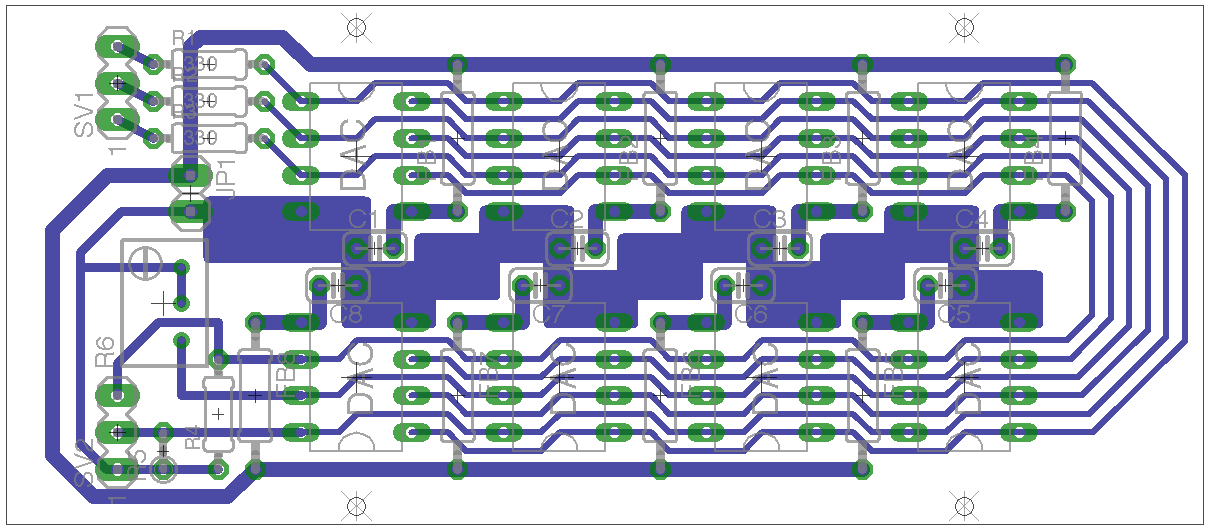
OK. Here is a slight alteration to the PCB using ferrite beads (I used resistors on Eagle for the beads as I couldn't find them in the library and couldn't be bothered to make the part). I have also changed the grounding for the DAC chips, it's more of a ground plane than a star ground, but it should be better I think. I still have pins 7 paralleled for now.
If I were to leave all pin 7s connected in parallel, what's the worst that will happen?
Loads of schematics connect them all together, I understand the tolerance on this pin is 2.2v +/- 0.1, so the voltage on this pin can be anywhere between 2.1 - 2.3. If these are all tied together, would this just mean that the DAC chips will increase in temperature more than if not?
Does the sound deteriorate if these pins are all connected?
If you tie the pins 7 together it just means the bias current isn't going to be very predictable and hence you'll probably need the trimmer once again. It won't have any impact on the sound - unlike your new ground plane which in my experience will sound congested on more complex music.
That is not a ground plane, it is a thick ground trace. A ground plane is an unbroken contigous plane underneath the signals that allows the return current to flow properly and thus maximise
signal integrity and reduce EMC problems, both of which are critical in getting the best out of a design. For digital signals a ground plane realy is mandatory these days with the ever increasing rise time
of digital signals. Ground planes are also used for analogue to again get the best results. Learning where and when the return current flows will help you picture the signal loop, and having a ground plane minimises the loop area and
thus lowers inductance. Star grounding is realy only for connecting system components such as amps, reciever CD etc, it realy has no place on low level signal PCB's.
The first link by John Wu covers the basics, and is a good start.
http://www.x2y.com/filters/TechDay0...log_Designs_Demand_GoodPCBLayouts _JohnWu.pdf
Grounding of Mixes Signal Systems
http://www.ti.com/lit/ml/slyp167/slyp167.pdf
http://www.analog.com/static/imported-files/application_notes/AN-1142.pdf
But the plan here is not to get the lowest overall inductance - if we'd wanted that we'd not be using ferrite beads (which most certainly add more inductance to the loop than a few cm of copper trace).
I agree though - a thicker ground trace does not constitute a ground plane
I agree though - a thicker ground trace does not constitute a ground plane
Update.....
My DIR9001 board arrived today from eBay so I got to work on it. As you can see from the picture, the LED is illuminated so the there is a valid signal being received. When the signal is removed, the LED goes out.
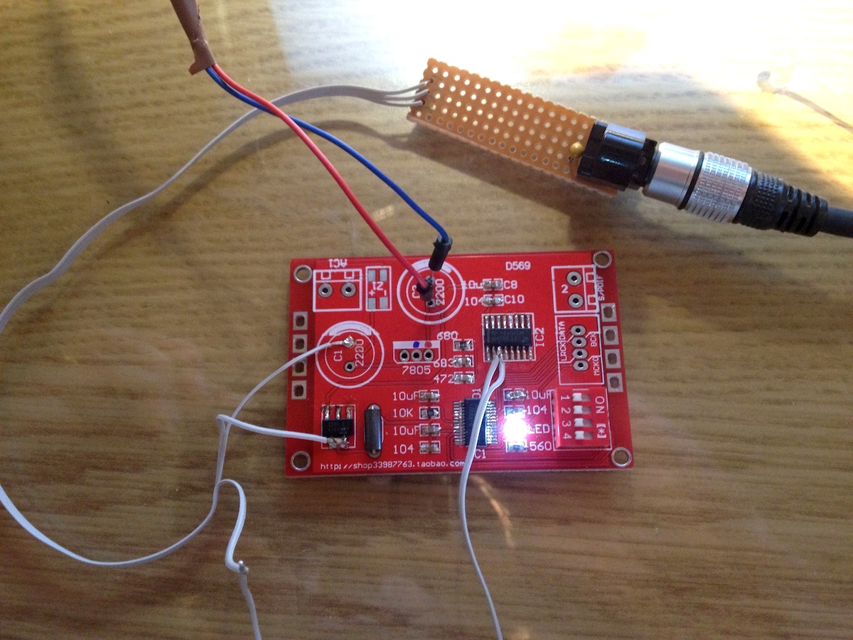
Just to test it, I am powering the board from a USB socket on my Mac (the red and blue cables, 5 volts). I am powering my TORX module from the output of the 3.3v regulator. I bent leg 3 of IC2 up and connected a small cable to the leg and one to the pad where it should be soldered too. This is what I will use to enable me to select either S/PDIF or my TOSLINK module. If you short them, the S/PDIF signal will be put through the DIR9001, if they are left open, the output from the TOSLINK module can be connected to the pad, therefore allowing it's signal to go to the DIR9001. This will be relay switched in my final project.
Just need my TAD1543A's to turn up now so I can get some actual audio out of the device.
The soldering wasn't as bad as I thought it would be. When soldering the DIR9001, I stuck the chip down with a piece of tape and put my iron (which currently had solder on it) on a few of the legs against the chip and drew the iron away from the chip. I did bridge a few legs a couple of times, but I used a clean iron and solder sucker to sort it out.
My DIR9001 board arrived today from eBay so I got to work on it. As you can see from the picture, the LED is illuminated so the there is a valid signal being received. When the signal is removed, the LED goes out.
Just to test it, I am powering the board from a USB socket on my Mac (the red and blue cables, 5 volts). I am powering my TORX module from the output of the 3.3v regulator. I bent leg 3 of IC2 up and connected a small cable to the leg and one to the pad where it should be soldered too. This is what I will use to enable me to select either S/PDIF or my TOSLINK module. If you short them, the S/PDIF signal will be put through the DIR9001, if they are left open, the output from the TOSLINK module can be connected to the pad, therefore allowing it's signal to go to the DIR9001. This will be relay switched in my final project.
Just need my TAD1543A's to turn up now so I can get some actual audio out of the device.
The soldering wasn't as bad as I thought it would be. When soldering the DIR9001, I stuck the chip down with a piece of tape and put my iron (which currently had solder on it) on a few of the legs against the chip and drew the iron away from the chip. I did bridge a few legs a couple of times, but I used a clean iron and solder sucker to sort it out.
I would eventually make my own PCB for the DIR9001. I have a question if someone could answer for me please:
The above PCB uses a Quadrupole differential line receiver just after for the S/PDIF input. From looking at the schematic, it is only actually using 1 of the 4 available on the chip. If I were to re-make the board myself, could I use something like this?
TEXAS INSTRUMENTS,UA9637ACP,DIFFERENTIAL LINE RECEIVER, DUAL | eBay
A DIP package is easier for me when making PCBs, I've already found a supplier of a DIR9001 pre-soldered to DIP28 adapter for only $9.
Is there anything I should look out for when choosing a differential line receiver?
OK. My TDA1543's turned up today and I built a simple test circuit to use one of them.
I connected the 8v power supply to pins 4 and 5 with a 10uF cap across them.
I connected 2k2 resistors from R-Out to GND and also L-Out to GND and 1K5 from Vref to GND.
Without anything else connected to the input, I am getting 3.6v DC on both right and left outputs? What have I done wrong?
I connected the 8v power supply to pins 4 and 5 with a 10uF cap across them.
I connected 2k2 resistors from R-Out to GND and also L-Out to GND and 1K5 from Vref to GND.
Without anything else connected to the input, I am getting 3.6v DC on both right and left outputs? What have I done wrong?
OK. I re-read this thread and done a bit more research. I found a simple circuit I will use just to try. I will feed the output into the -ve of an opamp, feed the +ve of the opamp with vRef and connect the output back to +ve input. Similar to the circuit diagram on this page:
AHDAC
AHDAC
Right. I tried a simpler option. I used a 2.2uF cap on each output and the sound from just one DAC is pretty impressive.
I then tried the same this with my 8 parallel DACs and the music is very very crackly. So I think I will have to disconnect all the pin 7s as abroxilto said earlier in the thread and connect them all separately to ground.
I then tried the same this with my 8 parallel DACs and the music is very very crackly. So I think I will have to disconnect all the pin 7s as abroxilto said earlier in the thread and connect them all separately to ground.
SORTED!
I pulled all the DAC chips out of my 8 chip PCB and tested, no crackling and good sounding music. I put another one in, slight crackling in the music so I adjusted the trimmer for vref and the crackling went. Right then, so I inserted all of the DAC chips again and adjusted the vref trimmer..... What a sweet sound now
Those 1543s do get pretty warm, will have to heat sink them against my case when I get around to building it
Just listening to it again now. Using an AppleTV3 streaming 320kbps music too the reciever board and then feeding my 8xTDA1543 board (with a piece of aluminium angle as a heat sink for now), into my LM4780 amp and then to my home made Derwent frual speakers with CSS EL70 full range drivers. It's sounding very nice indeed. I'll have to see how hot the little buggers get after an hour or so
What differences should I hear when changing the PSCK1 and PSCK0 switches on the receiver board. I can't hear any audible difference, what is the best way to have these set?
What differences should I hear when changing the PSCK1 and PSCK0 switches on the receiver board. I can't hear any audible difference, what is the best way to have these set?
Last edited:
- Status
- This old topic is closed. If you want to reopen this topic, contact a moderator using the "Report Post" button.
- Home
- Source & Line
- Digital Line Level
- DIY DAC....is this any good