Because I'm a fan of modding more than building from scratch, how about this:
ZJ DIR9001 DAC digital receiver board kit | eBay
I am still working on getting the schematics together, they'll be based on the DIR9001 because that's what I have running on my prototype which uses a front end which is a modded version of the board you originally linked to.
I don't have enough experience of the CS841X series of chips to know if they're any better than the DIR9001 - the one I've used does have the differential receiver on chip, whereas the DIR9001 needs to have a TTL level input. I recall one respected guru pointing out that Crystal (Cirrus) were daft to put schmitt triggers in their receiver coz this can only increase the jitter.
Why not consider the TDA1387 which is I2S compatible?
About reset circuits - I've not seen any on the chips I've used, but then I've not built any from scratch so I could have missed them. As far as I know the DIR9001 doesn't need one.
Hi Abbraxalito,
fro digital and low level analogue systems ground planes do give the best results, though double sided designs are done and do work adequetly, for ultimate signal integrity though of both analogue and digital a ground plane is best. Personaly I am not a fan of the extreme star grounding that seems prevelant in DIY audio as it is not the best way to do things. Point to point wiring is OK but with audio you are working with the frequencies where the return current path is changing from path of least resistance to path of least inductance, so a ground plane allows the return currents to follow their optimum path. Digital is all path of least inductance so it will always want to follow a path directly under the signal trace. The biggest problem with todays digital is the ever increasing rise times of even the most basic logic, it is this that determines whether it is high speed digital and the harmonic content of the square wave, so I always reccomend that high speed layout techniques are employedto give the best signal integrity and EMC compatability.")
fro digital and low level analogue systems ground planes do give the best results, though double sided designs are done and do work adequetly, for ultimate signal integrity though of both analogue and digital a ground plane is best. Personaly I am not a fan of the extreme star grounding that seems prevelant in DIY audio as it is not the best way to do things. Point to point wiring is OK but with audio you are working with the frequencies where the return current path is changing from path of least resistance to path of least inductance, so a ground plane allows the return currents to follow their optimum path. Digital is all path of least inductance so it will always want to follow a path directly under the signal trace. The biggest problem with todays digital is the ever increasing rise times of even the most basic logic, it is this that determines whether it is high speed digital and the harmonic content of the square wave, so I always reccomend that high speed layout techniques are employedto give the best signal integrity and EMC compatability.
fro digital and low level analogue systems ground planes do give the best results, though double sided designs are done and do work adequetly, for ultimate signal integrity though of both analogue and digital a ground plane is best.
So you mean 'best results' in terms of 'best measurements' or have you listened to the differences in sound?
Personaly I am not a fan of the extreme star grounding that seems prevelant in DIY audio as it is not the best way to do things.
Do you have links where the star grounding is extreme (other than my blog
)? I sometimes find myself encouraging people to be more extreme with their grounding... Point to point wiring is OK but with audio you are working with the frequencies where the return current path is changing from path of least resistance to path of least inductance, so a ground plane allows the return currents to follow their optimum path.
Yes I agree but I don't want return ground currents from other devices sharing the same paths - at least I find it doesn't sound as good. So its how to get the lowest inductance whilst minimizing ground impedance coupling.
Digital is all path of least inductance so it will always want to follow a path directly under the signal trace. The biggest problem with todays digital is the ever increasing rise times of even the most basic logic, it is this that determines whether it is high speed digital and the harmonic content of the square wave, so I always reccomend that high speed layout techniques are employedto give the best signal integrity and EMC compatability.
I take on-board what you're saying. My preferred route is always to avoid generating the fast edges in the first place - through use of as slow logic as possible and lower supply voltages. If I were using the newer kinds of DAC chips made in small geometry CMOS then I'd probably go your route, rather I confine myself to slower stuff with geometries above 1um typically.
Best signal integrity, which has to equate to best sound quality, though listening test I generaly get involved in are more formal, such as modified rythme tests (communication systems). Most of the stuff is instrumentation or controll where analogue is involved, so you dont listen but have to measure or listen for the big bang!. The star grounding I was refering to was some chip amps and pre-amp (low level circuits) where the ground looks like a squashed spiders legs (nice ariel).
I would use a term greater than extreme for your DAC reminds me of some of the processor boards that use to get wire wrapped in the early 90s, again these had point to point wiring on the return (gnd, 0V) and worked, but again had slower rise times. It use to be fun when a wire had to be changed!! Older slower logic was is easier, we would do digital boards on two layers many years ago with no problems, but these days the increase in rise times and the EMC polution levels mean that we have to use a minimum of 4 layers just to pass CE and FCC.
Have fun and keep up the 'extreme' DAC
I would use a term greater than extreme for your DAC
reminds me of some of the processor boards that use to get wire wrapped in the early 90s, again these had point to point wiring on the return (gnd, 0V) and worked, but again had slower rise times. It use to be fun when a wire had to be changed!! Older slower logic was is easier, we would do digital boards on two layers many years ago with no problems, but these days the increase in rise times and the EMC polution levels mean that we have to use a minimum of 4 layers just to pass CE and FCC.Have fun and keep up the 'extreme' DAC
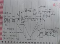
Power supply and input schematic for differential NOS DAC
Here's my sketched schematic for the first part of the DAC.
You'll note I'm paranoid about CM noise and have used two different kinds of CM chokes - CM1 is 3 1206 SMT type chokes in series to give 20uH of CM inductance, good to a few hundred MHz. CM2 is only good to about 10MHz. Having such filtering makes the DAC more tolerant of cheap transports (which mine certainly is!).
Attachments
I've ordered the DIR9001 input board as this seems like the easiest option. I want to add optical input to my DAC, so I will use a relay and switch the input into the DIR9001 from the S/PDiff input on the board and my optical receiver.
I've been looking on this forum and the net to find out what receiver I need, but am confused. Most people say that a TORX177 should be used! The data sheet says that the supply voltage is 5v +/-0.25v. If I want to supply 3.3v to my DIR9001, would I not be better off using a TORX147, which is 3v +/-0.3v?
I've been looking on this forum and the net to find out what receiver I need, but am confused. Most people say that a TORX177 should be used! The data sheet says that the supply voltage is 5v +/-0.25v. If I want to supply 3.3v to my DIR9001, would I not be better off using a TORX147, which is 3v +/-0.3v?
This worked well for switching between optical and BNC for me. But you may be looking for an all-on-one PCB approach.
http://www.diyaudio.com/forums/digi...kit-cs8416-ak4393-5532-a-206.html#post3110684
TOSLINK Optical Input to S/PDIF Module | eBay
http://www.diyaudio.com/forums/digi...kit-cs8416-ak4393-5532-a-206.html#post3110684
TOSLINK Optical Input to S/PDIF Module | eBay
Hope your DAC sounds as good as it looks
Would an optical to S/PDIF sound as good as a direct input from the TORX147 to the DIR9001? I mean, the signal has to be converted from the output of the TORX receiver to S/PDIF and then into the input of my eBay DIR9001 receiver board, instead of directly connecting the TORX147 to the chip.
Would an optical to S/PDIF sound as good as a direct input from the TORX147 to the DIR9001? I mean, the signal has to be converted from the output of the TORX receiver to S/PDIF and then into the input of my eBay DIR9001 receiver board, instead of directly connecting the TORX147 to the chip.
Thanks, the DAC sounds fantastic. Your question is what I meant about you wanting a single PCB. I don't have the knowledge to pull that off. There are however a minimum of components on the module I'm using. Shouldn't be that difficult to duplicate for someone with good circuit chops.
If I were to use 8 TDA1543A's in parallel, would I need to buffer the signals coming from the DIR9001? Or could I simply connect each input of the DACs together and let the DIR9001 drive them direct? I would add separate resistors for each chip and also a small cap across the supply of each DAC.
Load of people are saying they find the sound of the TDA1543 better than the newer CMOS versions, I assume the TDA1543A is of the same quality.
If you'd asked me at the beginning of last year I'd have given the same response - that I preferred the 1543. Since then I've discovered why it sounded better - because the glitches out of the 1545As were upsetting my I/V stage. I've developed a 'hardened' I/V stage now and the 1545/1387 sound distinctly better than the 1543 when the former are used with this stage. That corresponds to the datasheet too because 1543's measurements are none too pretty
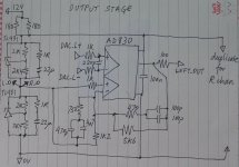
Here's the 2nd installment - the output stage which features the AD830 - my glitch-hardened output stage. It also incorporates an attempt at sin(x)/x correction.
<edit> About the heatsinking of 1543s - I'd not bother at lower supplies, say under 6V. Going above that it depends on what your case is made from, how well air flows around inside, all those kinds of details...
Attachments
Last edited:
If I were to use 8 TDA1543A's in parallel, would I need to buffer the signals coming from the DIR9001? Or could I simply connect each input of the DACs together and let the DIR9001 drive them direct?
On my DAC-AHs there's a CS841X and that drives 8 TDA1543s direct so I think the DIR9001 wouldn't have a problem. Use series resistors to damp down any reflections/ringing - 330R on each DAC should work OK.
This being for the 1543s? I seem to recall that being about the formula yeah but it depends to some extent on the power supply voltage you choose. People go for higher supplies to get higher output swings - which in turn need slightly higher value resistors. Since the fs Iout is 2.3mA for 2k2 you'd get 5V peak-peak which implies the maximum supply of 8V (since the swing is 3V below the supply). Running at 5.5V (for example) the resistor value you'd need would be 1k1.
- Status
- This old topic is closed. If you want to reopen this topic, contact a moderator using the "Report Post" button.
- Home
- Source & Line
- Digital Line Level
- DIY DAC....is this any good