Hello,
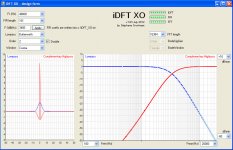
Did you know that a Linkwitz-Riley XO can deliver a perfectly reconstructed phase? From the attached .jpg it gets obvious that we are going to live a few more decades with Linkwitz-Riley crossovers, this time using FIRs.
The 4th-order LR (two cascaded 2nd-order Butterworth) exhibits a fair low amount of preshoot and ringing.
The phase and the amplitude are perfectly reconstructed, when adding the lowpass and the highpass.
This is something an analog Linkwitz-Riley XO cannot do.
This is something a digital IIR-based Linkwitz-Riley XO cannot do.
I went on www.linkwitzlab.com
Over there I have not found such FIR-based Linkwitz-Riley. Can somebody explain this to me? Where is it located?
Such FIR-based Linkwitz-Riley is easy to obtain.
You decide how many taps your FIR will be (101 taps in our case).
You decide about the sampling frequency (48 kHz) and the -3dB lowpass frequency (3400 Hz).
You apply the module function of the Butterworth lowpass, in function of the frequency.
You cascade two such module functions.
Code is here:
If Me.Lowpass_List.SelectedIndex = 7 Then 'Butterworth
Me.F_Label.Text = "F-3dB(Hz)"
Me.Order_List.Enabled = True
Me.Double_Box.Enabled = True
If Me.Order_List.SelectedIndex = 1 Then
n0 = 1
d0 = 1
d2 = 0
d4 = 1
d6 = 0
d8 = 0
d10 = 0
d12 = 0
End If
For i = 0 To N
F = FS * (i / N)
Fr = F / Fcut
GAIN(i) = n0 / ((d0 + d2 * Fr ^ 2 + d4 * Fr ^ 4 + d6 * Fr ^ 6 + d8 * Fr ^ 8 + d10 * Fr ^ 10 + d12 * Fr ^ 12)) ^ 0.5
If Me.Double_Box.Checked = True Then GAIN(i) = GAIN(i) * GAIN(i)
PHASE(i) = 2 * Math.PI * (MID * i / N) 'take FIR delay in account for the phase
Next
End If
The above code builds the iDFT GAIN array and iDFT PHASE array. Watch out the phase, it got defined as a pure delay equal to half the FIR delay.
You then execute the iDFT.
As result you obtain the time-domain impulse response, that you regard as the required lowpass FIR coefficients.
The complementary highpass gets computed, basing on the lowpass FIR coefficients.
The highpass FIR is the lowpass FIR with negative sign, with one notable exception which is the FIR midpoint highpass, where one must obey the rule:
highpass FIR midpoint = (1.00 - lowpass FIR midpoint)
This way, the reconstruction (lowpass + highpass) will equal a Dirac occurring on the FIR midpoint. Meaning that the reconstruction is perfect in amplitude, and in phase.
Add some windowing function if you want, and you are done.
IIR-based crossover: no thanks!
Any comments welcome.
Attachments
Last edited:
Very nice. Lots of thought. Now for the monkey wrench. Drivers. I can't remember the last time I had a mathematically symmetrical crossover in amplitude, let alone phase. We need to sum the results of the acoustic output of drivers at close to where they are very non-linear. All a big bag of tradeoffs. Active makes it easier, as you are not dealing with variable impedance of the load, the amp has to do that. Still, offset crossover points and different slopes are what I usually wind up with. ( DCX on bench).
So, how to use your analysis to include the asymmetry from the drivers? I believe, though have not played with it, Bodizio UE tries to do this. No idea if it is as comprehensive as you explain in your approach.
So, how to use your analysis to include the asymmetry from the drivers? I believe, though have not played with it, Bodizio UE tries to do this. No idea if it is as comprehensive as you explain in your approach.
- Status
- This old topic is closed. If you want to reopen this topic, contact a moderator using the "Report Post" button.