That's very interesting! Now we're getting into the topic! ")
First, *the* question How did you generate FIR coefficients for simulating a LR24? Would you mind sharing the coef file?
Can you explain the 128-sample delay on ch3?
Last question: could you measure the outcome?
[Edit] Another question: how do the 2 channels sum together?
First, *the* question
How did you generate FIR coefficients for simulating a LR24? Would you mind sharing the coef file?Can you explain the 128-sample delay on ch3?
Last question: could you measure the outcome?
[Edit] Another question: how do the 2 channels sum together?
Last edited:
That's very interesting! Now we're getting into the topic!
First, *the* question
Can you explain the 128-sample delay on ch3?
Last question: could you measure the outcome?
[Edit] Another question: how do the 2 channels sum together?
1) I use Acourate to generate the filters. I will send the files to you.
2) Prosessing delay seems to be double for mid compared to tweeter. mid has 512 taps and tweeter only half.
3) See attachment. I had to set the mic up and did not hit the same spot, so the result is not as good as it could have been.
best
Paal
Attachments
Nice Paalj
Not as good : you mean eg dips at 90 And 220 ? Did you try to correct them or is it just a choice not to
SpeedySteve
Great system you have, congrats (;-)
Did you try a set up to Check the Najda DAC And output stages ( stereo filter feeding your analog filters) part compared to your former DaC ? I would be glad to know about the sound caracteristics.
BR
Jean-Louis
Nice Paalj
Not as good : you mean eg dips at 90 And 220 ? Did you try to correct them or is it just a choice not to
BR
Jean-Louis
Hi Jean-Louis,
Because I did the first measurement yesterday and removed the mic I did not hit the same measurement spot today as I used yesterday. Therefore this "ragged" response. Anyway, I did no attempt to correct the 90 dip. The driver correction stops at 100Hz. Note that this is just for testing. It is not a good idea to try measuring down to 100Hz indoor but outside is 50cm of snow
best,
Paal
That's very interesting! Now we're getting into the topic!
[Edit] Another question: how do the 2 channels sum together?
Did not see this one.
Regardig the sum, see attachment.
Attachments
Nice Paalj
SpeedySteve
Great system you have, congrats (;-)
Did you try a set up to Check the Najda DAC And output stages ( stereo filter feeding your analog filters) part compared to your former DaC ? I would be glad to know about the sound caracteristics.
BR
Jean-Louis
Thanks. I do love it. Taken a while to put it together - continually evolving.
Well having taken the caps off the S2's drivers the sound has blossomed.
The Vitavox S2 driver in the range about 1 KHz to when it runs out of puff and ramps off nicely at about 12KHz, on the right horn is an amazingly clear and fast transducer. Capable of such tonal quality too.
It needs to be fed the right quality signal. So much is going on in that freq range. It is also a driver that is doing very nice things lower down the dB scale of the slopes - hence only putting it on BW 6dB/oct - lets it play all it can.
I am at present gobsmacked by how good the Najda piece of kit sounds.
I am not missing the passives - i did not quite think I would be saying that!
Hats of to Nick.
I have only tweaked the gains a bit and chosen slopes that gave a reasonably flat simulation/calc. Not got the measuring mic out yet... That will be next weeks work. Then there is the correction side of things to try. Better PSU? Let alone other OP amps...
What sort of core load is normal. I am at 44 and 38% on 96KHz and doing 8 channels.
I've ordered a IR sensor, and have an All-In-One remote that should do JVC and NEC codes.
Can't stop listening and wondering.
Last edited:
I'm just coming back quickly (!) to the FIR filters that Paal has designed. Paal sent me his coefs - I hope he won't mind if I post a few screenshots here.
So I've loaded his coefficients on Ch1 and Ch2:

One filter is 512 samples long, the other one is only 256 samples.
The design procedure for FIR filters often yields to impulse responses that extend to infinity in the past ... and in the future, with (luckily) most of the energy being at the time 0 (the impulse response appears here in red). Time 0 is the time of now.
No computer, regardless of how powerful, can compute the output of a infinitely long filter. And no computer can guess what the samples of the future are going to be.
That's right, the theoretic model requires to know what the sound was before you were born.
It also requires to know in advance what the sound is going to be long after you have died.
That's why we need to approximate this infinitely long filter by windowing its impulse response - i.e. keeping only a certain number of coefs and ignore the remaining ones.
So first thing we do, we keep N points of the impulse response symmetrically about time 0. This way we have a filter that expands only approximately N/2 coefs in the past and N/2 coefs in the future.
There's still this problem that the filter needs to know samples of the future. To go around this, we 'shift' the impulse response in the past so that the future becomes the present
The amount of shift is usually half the length of the impulse response, so for a 512-coef filter, the amount of shift is 256 samples. In clear, by shifting the filter so that we can implement it, we effectively introduce a delay of half the length of the filter.
This is why Paal introduced a delay of 128 samples on the tweeter channel. Indeed, the medium filter, by design, induces a delay of 256 samples meanwhile the tweeter filter a delay of only 128 samples. Thus Paal has time-aligned the outputs of both channels.
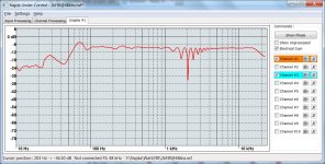
So here's what the frequency response of both filters is looking like:

As Paal explained, they combine a FIR approximation of a 4th order LR to some EQing.
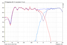
I asked Paal to show how the channels sum together. Here's what he showed:

I frowned quite a bit when I saw this. There's obviously something wrong with this crossover. Or something wrong with the graph.
The fact is, the Summing feature in the graph utility doesn't take the delay into account. So this plot shows what the sum would be if there had been no additional delay on the tweeter channel. (Rest reassured I will fix that asap).
So I cheated. I opened Paal's tweeter coef file and I inserted 128 'zeros' at the beginning of the file. These zeros act as a delay: indeed, during the first 128 samples, the modified filter ignores the incoming samples (it multiples them by the null coefs).
Finally, I reloaded the file and suppressed Paal's original delay. I had now the medium's 512-coef filter with a new tweeter 384-coef filter equivalent to Paal's original design.

Again, I checked how the channels were summing, and here's how it looks like:

Isn't it looking much better? If there was no EQing, the channels would sum flat.
Conclusion: I think this crossover has a good potential. I'm looking forward to read Paal's comments on his listening session !!
So I've loaded his coefficients on Ch1 and Ch2:
One filter is 512 samples long, the other one is only 256 samples.
The design procedure for FIR filters often yields to impulse responses that extend to infinity in the past ... and in the future, with (luckily) most of the energy being at the time 0 (the impulse response appears here in red). Time 0 is the time of now.
No computer, regardless of how powerful, can compute the output of a infinitely long filter. And no computer can guess what the samples of the future are going to be.
That's right, the theoretic model requires to know what the sound was before you were born.
It also requires to know in advance what the sound is going to be long after you have died.
That's why we need to approximate this infinitely long filter by windowing its impulse response - i.e. keeping only a certain number of coefs and ignore the remaining ones.
So first thing we do, we keep N points of the impulse response symmetrically about time 0. This way we have a filter that expands only approximately N/2 coefs in the past and N/2 coefs in the future.
There's still this problem that the filter needs to know samples of the future. To go around this, we 'shift' the impulse response in the past so that the future becomes the present
The amount of shift is usually half the length of the impulse response, so for a 512-coef filter, the amount of shift is 256 samples. In clear, by shifting the filter so that we can implement it, we effectively introduce a delay of half the length of the filter.
This is why Paal introduced a delay of 128 samples on the tweeter channel. Indeed, the medium filter, by design, induces a delay of 256 samples meanwhile the tweeter filter a delay of only 128 samples. Thus Paal has time-aligned the outputs of both channels.
So here's what the frequency response of both filters is looking like:
As Paal explained, they combine a FIR approximation of a 4th order LR to some EQing.
I asked Paal to show how the channels sum together. Here's what he showed:
I frowned quite a bit when I saw this. There's obviously something wrong with this crossover. Or something wrong with the graph.
The fact is, the Summing feature in the graph utility doesn't take the delay into account. So this plot shows what the sum would be if there had been no additional delay on the tweeter channel. (Rest reassured I will fix that asap).
So I cheated. I opened Paal's tweeter coef file and I inserted 128 'zeros' at the beginning of the file. These zeros act as a delay: indeed, during the first 128 samples, the modified filter ignores the incoming samples (it multiples them by the null coefs).
Finally, I reloaded the file and suppressed Paal's original delay. I had now the medium's 512-coef filter with a new tweeter 384-coef filter equivalent to Paal's original design.
Again, I checked how the channels were summing, and here's how it looks like:
Isn't it looking much better?
If there was no EQing, the channels would sum flat.Conclusion: I think this crossover has a good potential. I'm looking forward to read Paal's comments on his listening session !!
Last edited:
Thanks StevePaal,
It's under setting / bass and treble / untick enable.
How exactly do you create the IIR XO filter files. I have not got upto speed on that yet.
.
I think the best way to make the IIR filters are to measure the raw response from each driver and import them into Najda under control
I'm just coming back quickly (!) to the FIR filters that Paal has designed. Paal sent me his coefs - I hope he won't mind if I post a few screenshots here.
Conclusion: I think this crossover has a good potential. I'm looking forward to read Paal's comments on his listening session !!
Hi Nick,
I don't mind at all
The XO might have good potential. I cannot say the same of the speaker
I just trow some drivers together in an outdated boxI am using an Linkwitz Orion. That's an OB with huge requirement of EQ in low frequency range. Guess I have to wait for "Decimation" or similar
best,
Paal
I have been staring at switches for a long time at Digikey, and it is only slightly less grueling then reading this thread from start to finish. I would have swore this was several hundred pages long. Paid for my board today and was hoping for some input on parts. Switches, unlit or lighted? Power supply, case, etc. Any help would be appreciated.
Guess I have to wait for "Decimation" or similar
best,
Paal
Hi Nick,
Just found that Acourate does the decimation. up to 15x...
best,
Paal
I have been staring at switches for a long time at Digikey, and it is only slightly less grueling then reading this thread from start to finish. I would have swore this was several hundred pages long. Paid for my board today and was hoping for some input on parts. Switches, unlit or lighted? Power supply, case, etc. Any help would be appreciated.
I just some really cheap ones, but now I know this setup is a keeper, I'll be looking for a nicer action keypad, perhaps a bigger display too.
I like the way there are no LED's on when playing analogue too
Hi,
a free software to generate any kind of FIR filter,EQ.
rePhase | Free Audio & Video software downloads at SourceForge.net
you can have a look to the stop band ripple,according to Fs and taps number
a free software to generate any kind of FIR filter,EQ.
rePhase | Free Audio & Video software downloads at SourceForge.net
you can have a look to the stop band ripple,according to Fs and taps number
An externally hosted image should be here but it was not working when we last tested it.
Last edited:
I like the way there are no LED's on when playing analogue too
There is actually a quite useful LED, I found last night: AD CLIP. Correct that it should not light up during normal play.
There is actually a quite useful LED, I found last night: AD CLIP. Correct that it should not light up during normal play.
Yes
I found that One too.After PM with chaparK here is a relevant question that we thought merits further discussion in the thread:
Can the analog output gain be set per channel?
The answer is currently No.
To see why this might be of use consider a 3-way loudspeaker with different element sensitivities. From a digital standpoint it's desirable to have filters of roughly unity gain but this would be impossible if there is say 10dB difference in sensitivity between elements.
Another case could be that we wish to use an existing power amplifier that has a different voltage gain for one channel.
In my specific case the problem is made worse by the combination of these two factors.
So it seems I would need to increase the analog bass output from the board roughly 15dB to get unity gain digital filters.
Comments?
/K
Can the analog output gain be set per channel?
The answer is currently No.
To see why this might be of use consider a 3-way loudspeaker with different element sensitivities. From a digital standpoint it's desirable to have filters of roughly unity gain but this would be impossible if there is say 10dB difference in sensitivity between elements.
Another case could be that we wish to use an existing power amplifier that has a different voltage gain for one channel.
In my specific case the problem is made worse by the combination of these two factors.
- My bass amplifier is Class-D with voltage gain 26dB. The other channels are voltage gain 31dB.
- The crossovers need to be roughly 10dB hotter for the bass channel.
So it seems I would need to increase the analog bass output from the board roughly 15dB to get unity gain digital filters.
Comments?
/K
What sort of core load is normal. I am at 44 and 38% on 96KHz and doing 8 channels.
Regarding DSP load, any is good as long as it's below 100%.
You must make sure you don't go above 100% on any core. It's a drama otherwise.
Indeed, if you go above 100% on any core, the DSP will drop one sample and this will translate into halving the sampling frequency.
Now, what happens is that all the DSP parameters have been computed for that sampling frequency that you have selected when you created the Setup file. So if the effective sampling frequency is halved due to DSP overload, all these parameters will be wrong and the output will not be what you would expect.
There's one unused hardware led. I was thinking of using it to signal when the load goes beyond 100% on any core. How about that?
On the other hand, don't think that the DSP is happier when you lower the load. So as long as you are under 100%, any load is fine.
I've ordered a IR sensor, and have an All-In-One remote that should do JVC and NEC codes.
Cool! Let me know how it goes. I've a tested dozen of remote controllers, collecting some here and there - but more test is always better
...was hoping for some input on parts. Switches, unlit or lighted? Power supply, case, etc. Any help would be appreciated.
For switches I'd recommend unlit ones, of tactile type.
Hi Nick,
Just found that Acourate does the decimation. up to 15x...
I'm actually looking at how we could add decimation. I think we'll make it.
There is actually a quite useful LED, I found last night: AD CLIP. Correct that it should not light up during normal play.
So the AD Clip led is a status reported by the ADC itself. If the input level is too high, this is detected by the ADC and communicated to the micro and the control app. The only thing you can do to cure it is to lower the level of your analogue input.
All the other Clip leds are statuses reported by the DSPs. If there's too much gain in one part of the processing, the DSP will truncate the data word and set a flag. The cure here is to check your gain structure.
There are 3 processing clipping leds:
- Bass/Treble led: add headroom in the Bass/Treble dialogue
- Input processing led: Check your gain structure on the Input Processing tab.
- Output processing clip: Check your gain structure on the Channel processing tab.
(Note: the hardware leds will not tell you which channel or input precisely is clipping. But the control application will. On the monitor tab, each input has a dedicated software clip led, and each channel has the top segment in the VU-meter which acts as a clipping status).
In most cases, the lower sensitivity drivers are the ones in charge of the lower octaves, at these frequencies the human ear is much less sensitive to distortion (within limits of course).
In this case, a simple and straightforward line level voltage preamp (like Elliot sound's) can easily be used to amplify the relatively low output signal.
I think that ultimately, there are always compromises to be made, and this one is an easy one to make.
In this case, a simple and straightforward line level voltage preamp (like Elliot sound's) can easily be used to amplify the relatively low output signal.
I think that ultimately, there are always compromises to be made, and this one is an easy one to make.
After PM with chaparK here is a relevant question that we thought merits further discussion in the thread:
Can the analog output gain be set per channel?
The answer is currently No.
...
Comments?
/K
For the very good reasons you have detailed, I think it is definetely a must. Otherwise, one may need to add (expensive) pots/Lpads just before the loudspeakers, while we are trying to go digital as much as possible.
a free software to generate any kind of FIR filter,EQ.
rePhase | Free Audio & Video software downloads at SourceForge.net
Thanks Thierry I'll check this app soon.
After PM with chaparK here is a relevant question that we thought merits further discussion in the thread:
Can the analog output gain be set per channel?
The answer is currently No.
To see why this might be of use consider a 3-way loudspeaker with different element sensitivities. From a digital standpoint it's desirable to have filters of roughly unity gain but this would be impossible if there is say 10dB difference in sensitivity between elements.
Another case could be that we wish to use an existing power amplifier that has a different voltage gain for one channel.
In my specific case the problem is made worse by the combination of these two factors.
- My bass amplifier is Class-D with voltage gain 26dB. The other channels are voltage gain 31dB.
- The crossovers need to be roughly 10dB hotter for the bass channel.
So it seems I would need to increase the analog bass output from the board roughly 15dB to get unity gain digital filters.
Comments?
/K
Indeed we had a brief chat with Kazam and I thought we could discuss this topic here as this would be a great feature.
Not just specifically for Kazam's application, but also to provide more flexibility in the gain structure.
Currently, all the gains that you set in the processing tabs are DSP gains. I said to Kazam that it would be easy to add independent analogue gain everywhere in the system - except on the GUI (i.e. the pc app interface). So it's a bit tricky in the GUI because I must also support boards without analogue volume...
Right now, you can adjust globally the output level in the Board Configuration dialogue.
Would it be alright to replace this global adjustment with individual controls for each channel? Any thoughts?
- Home
- Source & Line
- Digital Line Level
- DSP Xover project (part 2)