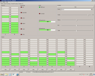
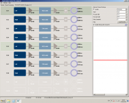
But since Nick likes photos, I thought I could post the current status:
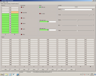
Power supplies in place, SE->BAL boards working, Arduino in place to switch between four spdif inputs (Twisted Pear Mux doing that) and display LED status.
True, I like pictures, thanks for posting
")
It's looking very good. Is it already operational?
Now another question - because "Settings" are not available in FIR engine, what to do with Analog Outs Configuration to increase max. output voltage from 1V to 3V?
Mike, the Settings sub-menu is not available when you're not connected. As soon as you connect, this menu becomes available in all modes.
The reason is that all these dialogues will need to update the board EEPROM. Obviously if your Najda is not connected, then that's not going to be possible.
I've just have not managed to save the settings in the long term. When I reboot my pc NUC forgets the selected settings for analog out and bass/treble Settings.
Frank, when you turn off your Najda board, put it in StandBy. That's at this moment that the Najda will store these parameters in the EEPROM so that they're automatically recalled when you switch the board on again.
True, I like pictures, thanks for posting
It's looking very good. Is it already operational?
YES! Thanks to your good help! Don´t have anything decent to connect it to though, but it´s playing through an old compact system.
I'd like to utilise the remote trigger from Najda to active power relay for amps, but am unsure of the connector type on the back panel. Can anyone advise how to connect to this?
Najda's remote trigger is well suited for driving external relays. Please check the interface chip datasheet: FOD852S.
For details on the connector, please see this post.
Cheers
Nick
Mike, the Settings sub-menu is not available when you're not connected. As soon as you connect, this menu becomes available in all modes.
The reason is that all these dialogues will need to update the board EEPROM. Obviously if your Najda is not connected, then that's not going to be possible.
Well, I made my first FIR 2-way xover and I was able lo load it as a preset. But! I don't have any signals on the outputs! What's going on?
Attachments
Last edited:
Mike,
You need to check the whole audio path.
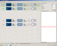
The signals are first crossing the Input Processing section. What do you have here?
By default, there's no coefficient loaded at this level. No coef = open circuit (no sound).
If you want a pass-through, you need to load a '1' for each path being used (in your case I suppose that's going to be Left and Right). This is all extensively documented in the NUC manual.
Cheers
Nick
You need to check the whole audio path.
The signals are first crossing the Input Processing section. What do you have here?
By default, there's no coefficient loaded at this level. No coef = open circuit (no sound).
If you want a pass-through, you need to load a '1' for each path being used (in your case I suppose that's going to be Left and Right). This is all extensively documented in the NUC manual.
Cheers
Nick
Hi Nick!Mike,
You need to check the whole audio path.
The signals are first crossing the Input Processing section. What do you have here?
By default, there's no coefficient loaded at this level. No coef = open circuit (no sound).
If you want a pass-through, you need to load a '1' for each path being used (in your case I suppose that's going to be Left and Right). This is all extensively documented in the NUC manual.
Cheers
Nick
You're absolutely right! Sorry for my impatience
I printed the Manual on the printer and I'll note all the important points with a red marker. Nevertheless, while I can not promise the absence of such a stupid questions in the future I'm starting to slowly fall in love with Najda Even without MUTE button.Doesn't look like a 3.5mm jack would fit in the remote trigger socket on Najda, from the data sheet, seems to take bare solid core wire (1.5mm). I suppose a 3.5mm socket could be wired in place instead - which would be more elegant than bare wires.A bit ot. but use ordinary 3.5mm jack, they fit with standard 12v trigger. But if you want powerconnectors, then maybe powercon from neutric?
I was looking at those Powercons the other day - any opinion on how they compare to IEC plug/socket? Would like to use for connecting high current amplifiers switched by contactor controlled by relay triggered from Najda.
Just to confirm my understanding- the relay control onboard Najda is just a switch, no voltage is supplied from the remote trigger socket. So suitable power source needs to be routed through Najda's remote trigger in order to drive a relay yes?Najda's remote trigger is well suited for driving external relays. Please check the interface chip datasheet:
Hi Nick!
You're absolutely right! Sorry for my impatience
No worries
Re. the mute button, we need to solve this. Have you checked the pin at the chip level (see my previous post on this topic)?
Just to confirm my understanding- the relay control onboard Najda is just a switch, no voltage is supplied from the remote trigger socket. So suitable power source needs to be routed through Najda's remote trigger in order to drive a relay yes?
Correct, that's an isolated switch.
Re. the mute button, we need to solve this. Have you checked the pin at the chip level (see my previous post on this topic)?
Hi Nick! Yes, I have checked, but I can't see nothing special, even with good magnifier. I don't really worry about this button at all
Hi guys!
Now about taps for FIR filters.
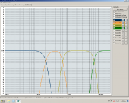
My goal is to create 4 filters for my 4-way loudspeakers:
1. LPF 150 Hz
2. BPF 150-700 Hz
3. BPF 700-7000 Hz
4. HPF 7000 Hz
What can you recommend, i.e. how many coefficients for each filter will be an optimum? All filters have to be LR 24 or better 48 db/oct. Also what about DSP Sampling frequency? Is it possible 96 kHz for my setup or only 48 kHz?
Regards, Mike
Now about taps for FIR filters.
My goal is to create 4 filters for my 4-way loudspeakers:
1. LPF 150 Hz
2. BPF 150-700 Hz
3. BPF 700-7000 Hz
4. HPF 7000 Hz
What can you recommend, i.e. how many coefficients for each filter will be an optimum? All filters have to be LR 24 or better 48 db/oct. Also what about DSP Sampling frequency? Is it possible 96 kHz for my setup or only 48 kHz?
Regards, Mike
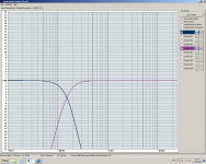
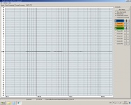
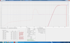
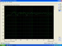
Well, I spent few hours to play with rePhase and NUC. Nick, your post helped me very much. What I got:
Is this point OK to start up?
Is this point OK to start up?
Attachments
I've been asked this question via PM:
Among the 4 output opamps, which opamp corresponds to what?
If you look at Najda from the rear (i.e. when the markings 22uF of the caps are turned the proper side for you to read), then from left to right:
- 1st opamp is for channels 3&4 (opamp near PCB edge)
- 2nd opamp is for channels 1&2
- 3rd opamp is for channels 7&8
- 4th opamp is for channels 5&6
Cheers
Nick
Nick, it will be good, if you will put this information here:I've been asked this question via PM:
Among the 4 output opamps, which opamp corresponds to what?
If you look at Najda from the rear (i.e. when the markings 22uF of the caps are turned the proper side for you to read), then from left to right:
- 1st opamp is for channels 3&4 (opamp near PCB edge)
- 2nd opamp is for channels 1&2
- 3rd opamp is for channels 7&8
- 4th opamp is for channels 5&6
Cheers
Nick
http://www.waf-audio.com/doc/Najda/Najda_SUG_Appendix_A.pdf
That looks like an excellent starting point. How does it sound?
Not all connections are ready yet. Let me couple days more
Which op amp....
Thanks a lot!!!:
I've been asked this question via PM:
Among the 4 output opamps, which opamp corresponds to what?
If you look at Najda from the rear (i.e. when the markings 22uF of the caps are turned the proper side for you to read), then from left to right:
- 1st opamp is for channels 3&4 (opamp near PCB edge)
- 2nd opamp is for channels 1&2
- 3rd opamp is for channels 7&8
- 4th opamp is for channels 5&6
Cheers
Nick
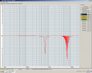
Thanks a lot!!!:
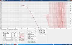
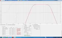
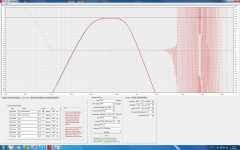
First result is very impressive! After separate measuring each driver necessary delay was added and also I made some correction for tweeter with Paragraphic Gain EQ in rePhase. The sound is amazing even with not the best amps for high-mids and highs. This FR was measured with the mic placed on the listening point
Attachments
Hi Nick!
Some time ago you promised about possibility to use IIR and FIR in the same setting. Is it still in development?
What about possibility to have more coefficients per channel, if the limit of 3580 coefficient for each DSP core not reached? For example, if I need only 3 hannels with FIR filters, can I have 1193 coefficients per channel?
- Home
- Source & Line
- Digital Line Level
- DSP Xover project (part 2)