There is an Oled screen on the resource list thread I posted about a page back. Was used in a build.
Tried to get it to work today but didn't work....
Nick, any chance of adding a tick box for OLED display? Details are here and apparently the differences are very minor:
OLED code

/K
Hi Nick
As you know we are preparing a little GB in France at Melaudia Forum and would like to create a professional looking case, possibly with engraved front side and professionally cut openings front and rear, in a 19" rack.
- Would a 1U unit heigth be enough for main board plus expansion board ?
- Could you publish a drawing of the rear panel with dimensions, so that we can integrate it in the panel design SW ?
- Could you publish side drawings of the board with the components size (eg in case some want to replace output caps)
Merci
Jean-Louis
Hi Nick
- Could you publish a drawing of the rear panel with dimensions, so that we can integrate it in the panel design SW ?
It is already available from the website:
http://www.waf-audio.com/doc/Najda/Najda_SUG_Appendix_C.pdf
It is already available from the website:
http://www.waf-audio.com/doc/Najda/Najda_SUG_Appendix_C.pdf
Yeah, you are right, how did I miss it ?
Tks
Tried to get it to work today but didn't work....
Nick, any chance of adding a tick box for OLED display? Details are here and apparently the differences are very minor:
OLED code
/K
+1
Yes please, it would be very nice to be able to use those OLEDs...
Hi Crumboo,
Nice work
Can you tell me which PSU you have used ?
Hi! I use the one from Mouser (mentioned earlier in this thread). Works good for now but I'll probably change to a linear PSU for the "real" build.
I'll probably change to a linear PSU for the "real" build.
Why?
Why?
Well I've heard that switching PSU's could potentially be noisy. Maybe I'll try different alternatives and evaluate before deciding.
This PSU is very convenient tough, small and just to plug in.
Well I've heard that switching PSU's could potentially be noisy.
That is a popular piece of audiophile folklore - not always based on fact.
Maybe I'll try different alternatives and evaluate before deciding
A good idea - a couple of ABX tests should quickly tell you if it makes any difference.
Rearding the channel linking:
Yes, as Urban pointed out, you can route any input to any channel. That's the 2nd topmost combobox on the right, or alternatively click on the source block (on the left) and use the arrow keys up/down.
Yes, this is precisely why I proposed the linking ch1/5, ch2/6, ch3/7, ch4/8, ch9/10.
Indeed, ch1/2/3/4/9 are processed by core 0 and ch5/6/7/8/10 are processed by core 2.
Thanks Jean-Claude, that's a very nice way of doing this. My only concern is where to locate this combo on screen, because the panel is already well populated.
However, there's additional hardware required in order to program the board. Indeed, you'll need a debugger for the micro, and a wiggler for the DSP.
Also, you'll need to install quite a few applications: programming environment + compiler for the micro, and an application for the DSP. The good thing is that most of these apps are free.
Congrats for your very nice build!
Regarding backlight, have you checked that power lines are not reversed? Backlight on these LCDs is just a led, so you don't need to connect any other pin in order to check it: if you supply power then it should light on.
Thanks, very happy you like it
I'll get one of those OLED and give it a try. Are you all using the same model mentioned in this thread or the resource thread that SAC has put together?
Yup it's all there Otherwise I confirm the board will fit into a 1U chassis. Total height is less than 35 mm.
That would not work that well. Channel one and five are both left channels.
I would prefer:
pair one - ch 1 and ch 2 (subs)
pair two - ch 3 and ch 4 (midbass)
and so on.........
It'd work just fine. Channel 5 is what you want it to be. Left, right, sum or diff.
Yes, as Urban pointed out, you can route any input to any channel. That's the 2nd topmost combobox on the right, or alternatively click on the source block (on the left) and use the arrow keys up/down.
yeah +1, but to get equal load on core 0 and 1 it is the best to have the other version (1-4 for one channel and 5-8 for the other). The load on my cores are exactly the same with this setup.
Yes, this is precisely why I proposed the linking ch1/5, ch2/6, ch3/7, ch4/8, ch9/10.
Indeed, ch1/2/3/4/9 are processed by core 0 and ch5/6/7/8/10 are processed by core 2.
About linking channels: why not doing that way:
"link to channel:" and box where you can select the channel you want to be linked
Thanks Jean-Claude, that's a very nice way of doing this. My only concern is where to locate this combo on screen, because the panel is already well populated.
There was a discussion some time ago on this topic, and I said I could make a template available to kick start those who want to load their own code.I'd just like to be able to play with the hardware, so as a minimum I'll need the basic drivers.
Is a schematics available, or at least a list of devices with addresses etc.?
However, there's additional hardware required in order to program the board. Indeed, you'll need a debugger for the micro, and a wiggler for the DSP.
Also, you'll need to install quite a few applications: programming environment + compiler for the micro, and an application for the DSP. The good thing is that most of these apps are free.
I finally had some time to put things together
[/URL]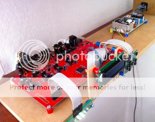
And it works... Unfortunately, I couldn't get my nice OLED display (which was left over for another project) to work. It has the exact pin-arrangement so I thought I would give it a try, but it was totally black and no sign of life at all. So I went down to the local store and bought a LCD display. For some reason however, there was no backlight at all so it's really hard to read. I checked the backlight supply pins and it seems to be in order (5V). Then I noticed that the maximum voltage for the background light was 4.5V according to the data sheet...so perhaps I killed it!?
Congrats for your very nice build!
Regarding backlight, have you checked that power lines are not reversed? Backlight on these LCDs is just a led, so you don't need to connect any other pin in order to check it: if you supply power then it should light on.
I've been playing music using Airport Express as source (optical connection) during the day and I think it sounds very very good!
Thanks, very happy you like it
However, I would really like to have a working OLED display so I just want to know if anyone has found a compatible one?
Tried to get it to work today but didn't work....
Nick, any chance of adding a tick box for OLED display? Details are here and apparently the differences are very minor:
OLED code
+1
Yes please, it would be very nice to be able to use those OLEDs...
I'll get one of those OLED and give it a try. Are you all using the same model mentioned in this thread or the resource thread that SAC has put together?
- Would a 1U unit heigth be enough for main board plus expansion board ?
- Could you publish a drawing of the rear panel with dimensions, so that we can integrate it in the panel design SW ?
- Could you publish side drawings of the board with the components size (eg in case some want to replace output caps)
It is already available from the website:
http://www.waf-audio.com/doc/Najda/Najda_SUG_Appendix_C.pdf
Yup it's all there
Otherwise I confirm the board will fit into a 1U chassis. Total height is less than 35 mm.I'll get one of those OLED and give it a try. Are you all using the same model mentioned in this thread or the resource thread that SAC has put together?
Great!!
Yes I believe so (Winstar WS0010 controller), mine is only in different color. You can find some more info here.
Yes, as Urban pointed out, you can route any input to any channel. That's the 2nd topmost combobox on the right, or alternatively click on the source block (on the left) and use the arrow keys up/down.
Seems to go much better if I actually open my eyes
Quote:
Originally Posted by paalj View Post
yeah +1, but to get equal load on core 0 and 1 it is the best to have the other version (1-4 for one channel and 5-8 for the other). The load on my cores are exactly the same with this setup.
Yes, this is precisely why I proposed the linking ch1/5, ch2/6, ch3/7, ch4/8, ch9/10.
Indeed, ch1/2/3/4/9 are processed by core 0 and ch5/6/7/8/10 are processed by core 2.
On the digital spdif outputs the pairing is 1-2, 3-4, etc. Is there any way to change that to get 1-5, 2-6, .......?
However, there's additional hardware required in order to program the board. Indeed, you'll need a debugger for the micro, and a wiggler for the DSP.
.
Can you maybe send a PM with more information about which debugger for the micro and the JTAG adapter for the DSP should I buy, and which development tools you use?
Can I buy a Najda without any installed connectors ?
Can I buy a Najda without any installed connectors ?
Hi SunShade
I recall I have seen that stated somewhere but cant find it again, you have to specify when ordering.
Hi Nick
Seems now the Najda is more and more a preamp.
Some easy questions, hope have not been answered before
- I would like to enter my FM Tuner in the Najda ADC and then go to my PC for recording some live concerts. How can I make this connection to PC, are there some SPDIF to USB convertors ?
- Is there an easy way to pick the analog signal just after the integrated DACs to feed external buffer (eg Tube, Pass B1...) ?
Could you publish the output stages design ?
- If we prefer to have the USB connector on the front panel, should we ask you not to solder it or just pick the signals and set a duplicate USB on front panel ?
Merci
Jean-Louis
You can find some more info here.
Alright Mattias, I'll get the same display and I'll let you know about how it goes ... in June because I won't be able sooner. Hope you can live with the standard LCD for now.
Could you solve the backlight issue?
Is the relay control a dry contact?
Hi Don, I'm not sure I understand the term 'dry contact'. Of the 2 contacts available, one should go to the ground of your external gear, and one should go to the coil of the relay - please see figure in section II.5 in the manual.
You can also refer to the datasheet of the optocoupler.
On the digital spdif outputs the pairing is 1-2, 3-4, etc. Is there any way to change that to get 1-5, 2-6, .......?
Unfortunately no, this is hard wired. I won't be able to change this.
Can you maybe send a PM with more information about which debugger for the micro and the JTAG adapter for the DSP should I buy, and which development tools you use?
For the micro, the cheapest solution is the STM Discovery kit. STM provides a development environment for free, and you can get a time-limited free license for a compiler.
For the DSP, you'll need a wiggler. Freescale has 2 debugging environments on their website. One is an old piece of software but still works fine, the other one is based on Eclipse. Both are free.
Writing code for the DSP is going to be easy and you will retain the volume and input switch which are controlled by the micro.
Writing code for the micro will be more problematic because your code will overwrite Najda's firmware when you load it.
I can deliver a board without any of the audio connectors mounted. The relay and USB socket however will be installed.Can I buy a Najda without any installed connectors ?
I need multichannel I2S input, with an input mixer that allows multiple routing any input channel to any output channel (e.g. INCH0 sent to OUTCH0 and OUTCH1).
Do you have any plan to update the software to allow that?
There is multichannel I2S input capability on Expansion Port 1 with one restriction: all channels must come from the same external device because they all share the same clocks (frame sync and bit clock).
Currently there's no plan for adding multichannel input support in the software. We can discuss this here.
This is not a problem but you will need an external USB sound card. There is a few cheap such sound cards, with digital in, that would do the job. One example is the (unfortunately discontinued) M-Audio Transit.- I would like to enter my FM Tuner in the Najda ADC and then go to my PC for recording some live concerts. How can I make this connection to PC, are there some SPDIF to USB convertors ?
Best is to get those signals at the coupling capacitors.- Is there an easy way to pick the analog signal just after the integrated DACs to feed external buffer (eg Tube, Pass B1...) ?
It's a standard MTBF topology, easy to reverse-engineerCould you publish the output stages design ?
Unfortunately I receive the board from the factory with the USB connector soldered onto it. In order to move the connector to the front panel, you will have to remove the USB socket on Najda.- If we prefer to have the USB connector on the front panel, should we ask you not to solder it or just pick the signals and set a duplicate USB on front panel ?
Power Supply
Hi,
while I am waiting for my Najda board to arrive I look at some PSUs
How about
1.) ASTEC DPT52
http://www.mouser.com/ds/2/132/dpt50_ds_1204757471-27209.pdf
External PSU, no switching frequency specified, minmum load 0.1A for +12V
2.) ASTEC NLP65-7608J
http://www.mouser.com/ds/2/132/nlp65_ds_1216436331-8473.pdf
Open Frame, 100Khz Switching Freq., requires minumum load to start up, foootnote 6
3.) ASTEC LPT 42
http://www.mouser.com/ds/2/132/lpt40series_ds_1184686732_ds-35130.pdf
Open Frame, 110KHz Switching Freq., requires minimum load 0.2A for +12V
If possible I would rather use an external PSU. Any opinion if 1) is OK?
I guess the minumum load is requires to not fall out of the specified range.
Nick: Any opinion if Najda would be sensitive to (hopefully only a bit) overvoltage?
Uwe
Alright Mattias, I'll get the same display and I'll let you know about how it goes ... in June because I won't be able sooner. Hope you can live with the standard LCD for now.
Could you solve the backlight issue?
That is really great to hear!!
And yes, the lines were reversed as you suggested. Strange, since I double and triple checked the data sheet of the LCD. Now it works perfectly!
Best regards,
Mattias
- Home
- Source & Line
- Digital Line Level
- DSP Xover project (part 2)