Is it possible to measure without both dsp and cap ? Or would that break the driver ?
Might not damage the driver at hifi vols / needed for measuring in a small room but is not a good idea. Esp with something as precious as Vitavox S2's.
The cap transfer function depends on impendance - it is text book only to fix impedance /resistor/
S2 isnt fixed impedance so transfer is bumpy.
I bet my wifethat once you eq response so it overlap in holm you wont heard any difference. When you start think that cap is better do it blind
Also i want to encourage everybody to use dsp in combination with passive element. I use DSP just to Attenuate - never to rise level - this way full digital dynamic range is preserved - and IMO - attenuate in digital is always better than plus EQ.
When you attenuate - f.e. low pass - signal with is most affected by DSP and physical DA limitation is in stop band - so potential flaws are many db below pass band. /i know that pass band is also manipulated - but i try to explain it simple/
When u make positive correction - the most attenuated signal is above other signal and potential flaws are more "hear-able"
Simple example HORN CD correction
Cap-resistor parallel together and this serial to driver - make nice HUMP in response tunable with cap and resistor value. Then little MINUS 1-2db correction in DSP = much better than PLUS 10-15 EQ in DSP. Also better S/N
because noise is attenuated by resistor.
Chapark - please if you can make some MATH comment.
ALSO real life DSP example /video for better understanding/
try DARKEN photo /DSP/ - photo is just darker - you dont see DSP artifact because they are hide in shadows.
TRY lighten Photo - you see steps in gradient - increased noise and other flaws - because of processing /steps/ and because you make original signal flaws more visible
Chapark - please comment my knowledge behind DSP math is very limited
That's interesting info - I'll try the reduce never increase and see. Level balance can come in gain / power amp side.
I am trying all sorts and learning = fun. Really need that extra 2 channels for proper 5 way to get to full grips with things
Are you using tubes as bufferts?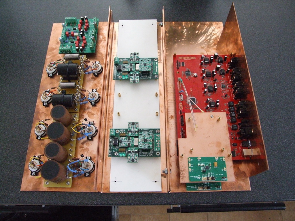
Out of parts for a while but it's slowly coming along
Are you using tubes as bufferts?
yes, for mids and high's, it's Broskies "unballancer". for the suboutputs I'm using TP's iVY-buffer.
Also i want to encourage everybody to use dsp in combination with passive element. I use DSP just to Attenuate - never to rise level - this way full digital dynamic range is preserved - and IMO - attenuate in digital is always better than plus EQ.
limited
I've just applied this to my 8 channels and after a quick listen / usual test tracks, it works! Great advice.
looks like you'll be correcting for the errors in the output stage too maybe pleasant sounding mate and impressive build with all that copper, duelunds etc, but there will be significant non linearities caused by that output stage that the DSP will be having to/trying to correct for. how much of that tube sound will be left unadulterated? or you will be keepikng it VERY simple with the cxrossover you program?
maybe its pleasing distortion, but its distortion all the same. It seems a strange thing to ask a DSP to do, ie. correct for itself. seriously, kudos on the commitment though. just trying to understand.
maybe pleasant sounding mate and impressive build with all that copper, duelunds etc, but there will be significant non linearities caused by that output stage that the DSP will be having to/trying to correct for. how much of that tube sound will be left unadulterated? or you will be keepikng it VERY simple with the cxrossover you program? maybe its pleasing distortion, but its distortion all the same. It seems a strange thing to ask a DSP to do, ie. correct for itself. seriously, kudos on the commitment though. just trying to understand.
Last edited:
looks like you'll be correcting for the errors in the output stage too
maybe its pleasing distortion, but its distortion all the same. It seems a strange thing to ask a DSP to do, ie. correct for itself. seriously, kudos on the commitment though.
Don't you have anything better to do
look, thats an honest question, did you think that through? see my edit above, i'm really trying to understand. the DSP will be working against the output stage and the output stage will be working against the DSP. how will you know whats caused by what? or you wont be asking the DSP to do much correction? just XO? I expect the tube buffer would sound quite good (not really my taste, but good all the same and a quality example of its type), I expect the DSP sounds quite good. it just seems together they are counterproductive and I wondered what your plan was.
like it or not, the DSP doesnt know what sound comes from where, so unless you are keeping the correction really minimal or non-existent, the DSP will see the error as something to correct for (thats what it is objectively, the DSP doesnt have taste)
you with me? low feedback or simple analogue stages will probably go better with low feedback, or simple digital correction. I figured you had a plan there given the obvious effort and expense.
sorry for the curiosity
edited arrangement.
Last edited:
Najda and WaveIO
A quick update on the WaveIO/Najda coupling. Sigi had already posted here his findings, but as Lucian (from Luckit, the WaveIO manufacturer) sent a board for testing, I thought that I'd report too.
So I'm happy to say there's no problem whatsoever. The picture below shows my quick and dirty test setup.

There are 4 pairs of signals running between the WaveIO and Najda: Data, Frame Sync and Bit Clock (all with their individual ground return) - and a 4th pair as described below.
The WaveIO is equipped with a bus isolator that must be powered with the external device's supply. That's the 4th pair of wires, in the present case +5VD and DGND pulled from Expansion Port 1 (you could also use +3.3V instead of 5V).
Last thing you can see on the pic is the purple wire loop. That's the connection of IS_EXT1 to DGND (both on Expansion Port 1). This is required to let Najda detecting a I2S input source.
A quick update on the WaveIO/Najda coupling. Sigi had already posted here his findings, but as Lucian (from Luckit, the WaveIO manufacturer) sent a board for testing, I thought that I'd report too.
So I'm happy to say there's no problem whatsoever. The picture below shows my quick and dirty test setup.
There are 4 pairs of signals running between the WaveIO and Najda: Data, Frame Sync and Bit Clock (all with their individual ground return) - and a 4th pair as described below.
The WaveIO is equipped with a bus isolator that must be powered with the external device's supply. That's the 4th pair of wires, in the present case +5VD and DGND pulled from Expansion Port 1 (you could also use +3.3V instead of 5V).
Last thing you can see on the pic is the purple wire loop. That's the connection of IS_EXT1 to DGND (both on Expansion Port 1). This is required to let Najda detecting a I2S input source.
...
you with me? low feedback or simple analogue stages will probably go better with low feedback, or simple digital correction.
Hi qusp
Am sorry I did not get your point why the tube buffer would not be good after the IV. What would you suggest alternatively ?
BR
Jean-Louis
The WaveIO is equipped with a bus isolator that must be powered with the external device's supply. That's the 4th pair of wires, in the present case +5VD and DGND pulled from Expansion Port 1 (you could also use +3.3V instead of 5V).
.
That's great news Nick. will there be any issues supplying 5v from the Najda on board regulator? I believe the WaveIO draws over 400mA
Najda board well received Nick, thank you. Beautiful card, very professionnally packaged.
Great to hear, thanks Jean-Louis!
That's great news Nick. will there be any issues supplying 5v from the Najda on board regulator? I believe the WaveIO draws over 400mA
So this 5V supply I was mentioning is just the isolator chip supply (IL715, see the WaveIO doc for details). The WaveIO board in my setup is powered by the laptop USB port.
If you don't want to power the WaveIO via USB, you should pull a wire from the power supply. +5VD on Najda doesn't go through a regulator, but through a small inductance which is rated for 320 mA. So if you power the WaveIO from Najda's 5VD, you might fry this inductance...
(OT: I'll be away until 17 JUN, might not have internet access until then
 )
)For US buyers
GECA40AG SL Power Electronics Manufacture of Condor/Ault Brands | 271-2531-ND | DigiKey
is a more viable option as the ripple at 5V rail is only 50mV
This TVS diode between ground and 5 volt will offer better OVP(5.1V) than even expensive SMPS units.
http://www.digikey.com/scripts/DKSearch/dksus.dll?Detail&itemSeq=131973328&uq=635066226371537632
Perhaps a shunt regulator may be added to filter out the noise.Not sure how to change it for 5 Volt
Finesse Voltage Regulator Noise!
(OT: I'll be away until 17 JUN, might not have internet access until then
Hello Nick.
I just ordered a second "Najda", will you take care of that after 17/6 ?
Hello Nick.
I just ordered a second "Najda", will you take care of that after 17/6 ?
Hi Bengt, I've sent you an email.
Nick
- Home
- Source & Line
- Digital Line Level
- DSP Xover project (part 2)