Whilst I haven't bought one (yet) I think that separate on/off commands are essential to get a group of equipment to behave the way you want. Without this, if any one piece of equipment is in a different state to the others, for whatever reason, then it needs a physical press to get it back in sync. With discrete on/off codes all the equipment gets cleanly set to the same state- Individual IR commands for each source (Shaun: I haven't heard any echo to your request re separate IR commands for On/Off...)
Sorry to hear that Steve, you've been quite unlucky with 2 faulty displays
Re. the expansion board, you only need 2 more analogue outs, correct? (There were talks about adding 6 more analogue outs a long time ago, don't know though if this is still actual).
Nick
Only one display was faulty; the Maplin, I mean Muplin one
")
I am currently eyeing the OLED offerings as they seem to be way nicer than LCD with LED backlight...
e.g:
https://encrypted-tbn1.gstatic.com/...f6nFrhbnTNL3q4DVa5L2f5nQSgUU1z7nu7QWmFapdcq7J
Might have to get one for the nice case I am getting...
Re: analogue outputs. I personally only need 2 more to make a 5 way.
Nobody in horn land is going to need 6 more!
I think 6 way is a possibility though - at the; For one day only;
GoodSoundClub - Romy the Cat's Audio Site - For one day only
gig, we really needed a pair of tapped horns to give the really low stuff.
Those enormous bass bins only played down to 35Hz. Once you have heard tapped 20Hz you really need it and want to share it
A couple of 15-40Hz would have been perfect and really amazed folk... next year?
So 4 more for me... I think 6 would push the processor to hard too - unless the expansion board has only board processing power.
Microtips Technology LCD Display 2 x 16 MTC S16204A 2 Lines x 16 Character | eBay
Pin designation:
Pin 1: Vc----------------?????
Pin 2: Va----------------?????
Pin 3: GND---------------1
Pin 4: VDD---------------2
Pin 5: VLC---------------?????
Pin 6: RS----------------4
Pin 7: R/W---------------5
Pin 8: E------------------6
Pin 9: Data 0-------------7
Pin 10: Data 1------------8
Pin 11: Data 2------------9
Pin 12: Data 3------------10
Pin 13: Data 4------------11
Pin 14: Data 5------------12
Pin 15: Data 6------------13
Pin 16: Data 7------------14
This project has been on the backburner for some time but now I've
started it up. Ran in to a problem rigth away. The display pin connections
wasn't named the same way so now I'm sure I'm putting it together the rigth
way.
Could someone tell me where pin 1,2 and 5 would connect to Najda ?
Seems that the display only has one "gnd" as well. Would both pin 1 and 16 connect to pin 3 at the display?
I found this helpful in mapping;
Najda pinout

Generic display pinout with common use abbreviations

The white on black displayfrom Polish seller, I just fitted was pin for pin the same as Najda.
The Maplin one had pin 15 and 16 as 1 and 2, and the rest following on from there.
As Nick says; you have found other mixes are out there.
VC and VA are new to me.
Last edited:
I thought that pinout was standard, but when I got mine from the same Polish supplier I found out that it have pin 1 and 2 reversed
ART New LCD 2x16-F with LED b/l - W1B (HD44780) H=30mm [ABC016002F11-BIW-R-03] | eBay
Datasheet
.
ART New LCD 2x16-F with LED b/l - W1B (HD44780) H=30mm [ABC016002F11-BIW-R-03] | eBay
Datasheet
.
.Nobody in horn land is going to need 6 more!
Steve,
- Maybe if you have two systems you want to compare or have them in two different rooms, or if you have more than 2 channels ?
Charpak
- May you please explain what is the mix of IIR and FIR ?
- What is the limiting factor you are experimenting now for >># of taps
CPU or Memory ?)- Is it (will it be) possible to upgrade memory on the MB itself or on the expansion board, or add a second processing unit ?
- Custom IIR, you mean filter types that are not butterworth or LR ?
BR
Jean-Louis
Steve,
- Maybe if you have two systems you want to compare or have them in two different rooms, or if you have more than 2 channels ?
BR
Jean-Louis
Ah yes; two rooms, of course
Re: analogue outputs. I personally only need 2 more to make a 5 way.
Nobody in horn land is going to need 6 more!
I think 6 way is a possibility though - at the; For one day only;
GoodSoundClub - Romy the Cat's Audio Site - For one day only
gig, we really needed a pair of tapped horns to give the really low stuff.
Those enormous bass bins only played down to 35Hz. Once you have heard tapped 20Hz you really need it and want to share it
A couple of 15-40Hz would have been perfect and really amazed folk... next year?
So 4 more for me... I think 6 would push the processor to hard too - unless the expansion board has only board processing power.
Alright - but the deal is 2 or 6, 4 is not an option
In short: 2 more outputs, we could make this happen shortly.
6 more outputs would take much (much much actually) longer.
- May you please explain what is the mix of IIR and FIR ?
- What is the limiting factor you are experimenting now for >># of taps
- Is it (will it be) possible to upgrade memory on the MB itself or on the expansion board, or add a second processing unit ?
- Custom IIR, you mean filter types that are not butterworth or LR ?
Website updated
Easy then for me.
Two is perfect.
10 outputs is more than
any? other dsp dcx I believe
and meets / exceeds the needs
of most.
If you have 2 rooms, buy another
Najda and chain to solve the problem elegantly.
6 might be nice one day as I may
try an injection channel, but not right now. If I do it could be analogue for the time being.
Regards
Steve
Last edited:
I'm going for this, and hoping for it to work:
Microtips Technology LCD Display 2 x 16 MTC S16204A 2 Lines x 16 Character | eBay
Pin designation:
Pin 1: Vc----------------16
Pin 2: Va----------------15
Pin 3: GND---------------1
Pin 4: VDD---------------2
Pin 5: VLC---------------3
Pin 6: RS----------------4
Pin 7: R/W---------------5
Pin 8: E------------------6
Pin 9: Data 0-------------7
Pin 10: Data 1------------8
Pin 11: Data 2------------9
Pin 12: Data 3------------10
Pin 13: Data 4------------11
Pin 14: Data 5------------12
Pin 15: Data 6------------13
Pin 16: Data 7------------14
There is no pinconfiguration marked for the ir remote, just "1".
The one I have has markings, Dat1, vcc and gnd.
Hi Bengt,
See section I.5 in the manual.
Nick
Quote:
Originally Posted by DSP_Geek View Post
Re a limited number of taps, one can do complementary highpass and lowpass FIRs by running a unity-gain odd-order lowpass linear-phase filter with N taps, then subtracting the full range input signal delayed by (N-1)/2 samples. For example, use a 401 tap LPF as the generator function, subtract the input delayed by 200 samples to obtain the HPF, and you're good to go. That more or less halves the computational load.
I remember you already posted this idea earlier. Please accept my apologies for not answering earlier.
There's however a problem I can see with your approach, it's that indeed the filters are complementary. Most of the time, FIR specifications include driver EQing (see Paal's examples) so complementarity is actually not desired. Please correct me if I misunderstood.
Quote:
I'd recommend against FIRs for low frequency room correction. Room gain is minimum-phase, as with other physical processes, so a parametric EQ does the job beautifully while consuming far fewer clocks.
@Chapark: would you be interested in a minimum-phase resampler?
Can you please develop?
CROSSOVER:
First let's look at complementary filters. Let's start by assuming no correction (we'll get to that later) and a 3 way system. The bass output is set up with a standard LPF FIR, the mid is driven by the HPF complementary to the bass filter, followed by a standard LPF for the upper rolloff, and the tweeter is driven by a standard HPF. This looks like a typical 3 way crossover, with the exception of using complementary FIRs between the bass and mid outputs. Why would we do such a thing? Let's take an example, with crossovers at 200 Hz and 3000 Hz. The 200 Hz FIRs might be 750 taps long while the 3000 Hz FIRs would be 50 taps long (in keeping with the observation that FIR lengths are more or less proportional to the inverse of their cutoff frequencies). Running separate FIRs for all sections yields 750 taps for the bass, 750 + 50 taps for the mids, and 50 taps for the highs, for a total of 1600 taps. Using complementary filters gives 750 taps for the bass, 50 taps for the mids (assuming trivial computation for the complement), and 50 taps for the highs, for a total of 850 taps. You save almost half the clocks.
Now, of course, people want to correct response aberrations in their speakers, and the crossover with its FIRs is a logical place to look. However, one must consider exactly what is being corrected. Speakers below their breakup frequency have few high-Q resonances, so one doesn't need high resolution in the frequency domain to fix whatever problems may occur. In that case an IIR solution is quite sufficient. Extending the response of a mid down an octave or two with a Linkwitz transform, for example, is entirely doable. Now consider that cone breakup for a 12 inch woofer is a few hundred hertz and about a kilohertz or two for an organic cone midrange, and one can see extreme frequency resolution is not overly critical. However, it'd still be nice to flatten the midrange with a FIR; that's where the separate lowpass FIR on the mid section comes in, since the correction can come in on the shorter FIR without disturbing the complementary filters between the bass and mid. Even if you triple the length of the LPF on the mid, so frequency resolution is 44100 / 150 = ~300 Hz, you're still running 950 taps for the corrected system as opposed to 1600 taps for the naive implementation.
RESAMPLER:
Apparently, under critical listening, people seem to prefer minimum-phase FIRs for reconstruction filters. I haven't tested them extensively in that use, but it might be an amusing option for DIYers to try. The impulse response looks like a sharp cutoff IIR (which makes sense since it's a minimum phase filter just like an IIR) with about the same total amount of ringing as the equivalent linear phase filter, but all pushed to the right. However, one doesn't get away with the linear-phase half-band resampler trick of having every even sample merely be the copy of the input while the odd samples are processed through the FIR, because a minimum-phase filter has no zeroes in the impulse response as half-band linear-phase filters do. On the other hand, you must zero-stuff the input so only half the computation is needed for each 88200 Hz sample. I'm already using a minimum-phase FIR in another application (day job, can't talk about it) and it works quite nicely. I could fire off a set of coefficients for you to build a resampler on if you want to give it a go.
In short: 2 more outputs, we could make this happen shortly.
6 more outputs would take much (much much actually) longer.
ESAI limitations, eh?
BTW, have you considered daisychaining multiple DSPs? After the first extra one it's pretty well plug & play from what I understand.
CROSSOVER:
[...]
RESAMPLER:
[...]
Hi DSP_Geek,
Thanks for this interesting reading. Right now we have defined other priorities but these are good ideas for future developments.
No. 2 extra processing channels are already available in the system, and a 2-channel analogue expansion could easily take profit of it.ESAI limitations, eh?
More channels would require a new software+firmware. That is actually the limitation in time and cost.
Hmm not really. What would you daisy-chain DSPs for?BTW, have you considered daisychaining multiple DSPs? After the first extra one it's pretty well plug & play from what I understand.
No. 2 extra processing channels are already available in the system, and a 2-channel analogue expansion could easily take profit of it.
More channels would require a new software+firmware. That is actually the limitation in time and cost.
Hmm not really. What would you daisy-chain DSPs for?
Yeah - I see the blanked out sections in the menus for these two
Daisy-chaining you would have to control the vols of each unit separately I think? - Not a solution for me - could work nicely for multiple room setups though.
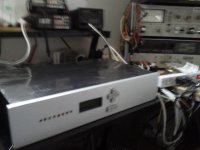
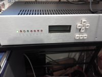
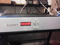
It works
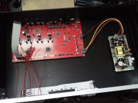
Proof positive anybody can assemble one. Finding my eye glasses was the hardest part. All systems nominal. The green LED on the left is power on light so I know to shut it down when I quit. I searched Ebay for a Hitachi hd44780 compatible LCD, it works perfect. Case is from DIYAUDIO.com Working on filters now.
Proof positive anybody can assemble one. Finding my eye glasses was the hardest part. All systems nominal. The green LED on the left is power on light so I know to shut it down when I quit. I searched Ebay for a Hitachi hd44780 compatible LCD, it works perfect. Case is from DIYAUDIO.com Working on filters now.
Attachments
- Home
- Source & Line
- Digital Line Level
- DSP Xover project (part 2)