Btw, dear bigpandahk, I probably shouldn't be doing this to you, since you appear to have your hands full with the power supplies, but I have been experimenting with the Arduino Due as a controller and am pretty happy with the results.. The operation is now much snappier. Take a look at this comparison video that I made:
Arduino MEGA vs. Due - YouTube
You may notice that the startup is pretty much instantaneous (ok, no one cares, but still..), the volume control is extremely fast and the input changes are close to instantaneous as well. I'll be sticking with the Due for my implementation. I only have to find out why the rotary encoder is no longer working (it probably has something to do with the way the Due handles interrupts.. I'll look into it).
Very nice, very tempting.
How did you connect the Mega & the Due to the screen without the shield, when I tried that it didn't. are you just wiring direct from the screen to the board, a picture would be great
")
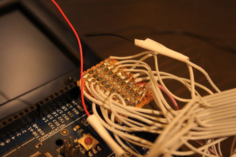
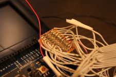
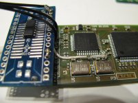
I made this adapter for the Mega:

It is just a bunch of 10K resistors connected to all of the signal pins.
In case of the Due, it is even simpler, since it uses 3.3V logic so no resistors are necessary:

Can't see the pictures.

That's strange.. let me try this again:
Ah, that's where I went wrong, no 10K resistors.
In the end I soldered pins onto the back of the Mega so I could get access to the other pins, it has worked out pretty well, certainly cut down on the wires.
Attachments
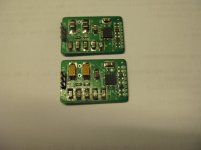
finally fixed the damaged 4700 PCB and built two 5V LDO with Ian's boards.
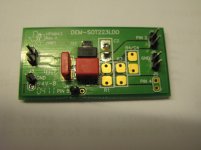
I also bought some PCB from Ti which suitable for most SOT223LDO, will use this to power the relay boards.
Next is to modify the Amanero using 4700LDO and re-sync the clock.
Dimdim, any finding on the Arduino Due interrupt?
I also bought some PCB from Ti which suitable for most SOT223LDO, will use this to power the relay boards.
Next is to modify the Amanero using 4700LDO and re-sync the clock.
Dimdim, any finding on the Arduino Due interrupt?
Attachments
I'm afraid that I haven't had much time to thoroughly troubleshoot the interrupt issue.
I have noticed that the Due requires a slightly different syntax of the attachInterrupt function (since it is capable of attaching an interrupt to any of its pins) and have made the necessary changes in the code, but it hasn't solved the problem. I will have to perform more extensive testing.
I have noticed that the Due requires a slightly different syntax of the attachInterrupt function (since it is capable of attaching an interrupt to any of its pins) and have made the necessary changes in the code, but it hasn't solved the problem. I will have to perform more extensive testing.
I'm afraid that I haven't had much time to thoroughly troubleshoot the interrupt issue.
I have noticed that the Due requires a slightly different syntax of the attachInterrupt function (since it is capable of attaching an interrupt to any of its pins) and have made the necessary changes in the code, but it hasn't solved the problem. I will have to perform more extensive testing.
Thanks Dimdim for your reply, waiting for your good news.
I modified the Amanero today but don't have time to test.
Happy new year to all diyaudio members.
Attachments

Very nice! You are very good soldering those tiny components...
Thanks glt
Without the clear description in your blog, I wouldn't know how to implement the mod.

Hi all,
I am stuck with a problem I hope someone can help me with.
After connecting my Fifo to my M2Tech Hiface evo (I2S output), my BII at the outlet of the dual clock and powered the Fifo with 5VDC. Everything looks ok but it doesn't play music, just silence.
My connection with Hiface evo.
M2Tech Hiface evo out: → Fifo in:
2,4,6,8) Ground → GND
1) SDATA → SD
3) LRCK (FS) → WS
5) SCLK (BIT CLOCK) → SCK
7) MCLK (Not connected)
My connection to BII.
Dual clock out → BII in:
Gnd → GND
SD → D2
WS → D1
SCK → DCK
MCLK (Not connected) since I uses the BII clock.
The fifo LED’s work perfectly and they seems stable. But no music comes out.
When connected and music played the Fifo led indicate locked signal. If I disconnect input signals and the led give the correct respons (the led goes black). The strange thing is that the led for Fifo buffer empty lights up (stable) even when music is played.
On the BII the led indicates that a signal has been locked and everything looks ok.
On the clockboard led for 512 and 44,1 kHz is shining.
You will find a manual on how to use I2S for M2Tech Hiface evo here: http://user.tninet.se/~pst442t/hiface_evo_i2s.pdf
The manual for Buffalo II here: http://user.tninet.se/~pst442t/Buffalo_II_User_Manual_v1.0.pdf
Greatful for all help I can get!
For info: My BII plays perfectly if the signal goes directly from Hiface to BII.
Hi all,
I am stuck with a problem I hope someone can help me with.
After connecting my Fifo to my M2Tech Hiface evo (I2S output), my BII at the outlet of the dual clock and powered the Fifo with 5VDC. Everything looks ok but it doesn't play music, just silence.
My connection with Hiface evo.
M2Tech Hiface evo out: → Fifo in:
2,4,6,8) Ground → GND
1) SDATA → SD
3) LRCK (FS) → WS
5) SCLK (BIT CLOCK) → SCK
7) MCLK (Not connected)
My connection to BII.
Dual clock out → BII in:
Gnd → GND
SD → D2
WS → D1
SCK → DCK
MCLK (Not connected) since I uses the BII clock.
The fifo LED’s work perfectly and they seems stable. But no music comes out.
When connected and music played the Fifo led indicate locked signal. If I disconnect input signals and the led give the correct respons (the led goes black). The strange thing is that the led for Fifo buffer empty lights up (stable) even when music is played.
On the BII the led indicates that a signal has been locked and everything looks ok.
On the clockboard led for 512 and 44,1 kHz is shining.
You will find a manual on how to use I2S for M2Tech Hiface evo here: http://user.tninet.se/~pst442t/hiface_evo_i2s.pdf
The manual for Buffalo II here: http://user.tninet.se/~pst442t/Buffalo_II_User_Manual_v1.0.pdf
Greatful for all help I can get!
For info: My BII plays perfectly if the signal goes directly from Hiface to BII.
Hi Karvid,
Can you post pictures of your hookup?
Thanks,
Ian
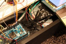
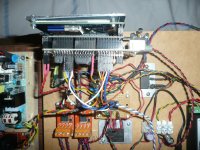
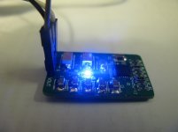
I add som pictures of my setup.First picture without inlet and outlet connected and in the second it is connected and powered up (trying to play music).
Note only one of the super shunt regulators is used.
Sorry about the format. I do not now how to make mini pictures..
An externally hosted image should be here but it was not working when we last tested it.
An externally hosted image should be here but it was not working when we last tested it.
Note only one of the super shunt regulators is used.
Sorry about the format. I do not now how to make mini pictures..
Last edited:
I add som pictures of my setup.First picture without inlet and outlet connected and in the second it is connected and powered up (trying to play music).
Note only one of the super shunt regulators is used.
Sorry about the format. I do not now how to make mini pictures..
Picture is OK.
It seems that the 7Pin PH2.0 I2S bridge cable connector on the clock board side has a bit loose. Can you confirm?
Ian
Ian,
I have double checked all connectors. And they seems all to be well connected. As well as the clocks.
After som handling has the led for empty buffer gone out (doesn't shine any more).
But if I disconnect the signals the Led says no longer locked signal and the buffer is empty. When I connect signal the led for locked signal is shining bright again and the buffer doesn't say emty any more (neither say the led that the buffer is full). So according to the led everthing is working.
This might be because I connected all of the gnd cables at input. I will try to do the same at the outlet and see if this will make a different.
- Status
- This old topic is closed. If you want to reopen this topic, contact a moderator using the "Report Post" button.
- Home
- Source & Line
- Digital Line Level
- Build Thread for TPA BIII + Ian Async I2S FIFO + OPC NTD1 + Salas SSLV