After installed Ian's isolator board, the bass become much clear and powerful. I am waiting for the i8605 for the additional isolation on the I2C bus.
Today, receive the battery management board and will assemble it ASAP.
Unfortunately, my DAC has a new problem, actually it should be old issue but happen more frequent. When I used the Legato for couple of days, I found its temperature is abnormally high. Some resistors reach 75 deg. C after 20-30 minutes operation. I have raised this query in the TPA support forum but was told it is normal.
Now, I believe the high temperature already damage some component(s). Last month the Legato start to fail after couple hours, but now it can only survive for several minutes.
Both channels have no sound when fail, any suggestion to trace the problem? Please!!
After installed Ian's isolator board, the bass become much clear and powerful. I am waiting for the i8605 for the additional isolation on the I2C bus.
Today, receive the battery management board and will assemble it ASAP.
Unfortunately, my DAC has a new problem, actually it should be old issue but happen more frequent. When I used the Legato for couple of days, I found its temperature is abnormally high. Some resistors reach 75 deg. C after 20-30 minutes operation. I have raised this query in the TPA support forum but was told it is normal.
Now, I believe the high temperature already damage some component(s). Last month the Legato start to fail after couple hours, but now it can only survive for several minutes.
Both channels have no sound when fail, any suggestion to trace the problem? Please!!
Please go through the schematics of the battery board before assemble. Too many options for a simple board
") . As well as the isolator board. I'm afraid you may need the pull-up resistors for the I2C buses if they were not included on both DAC and controller side.
. As well as the isolator board. I'm afraid you may need the pull-up resistors for the I2C buses if they were not included on both DAC and controller side.Ian
Hello bigpandahk,
I just grabbed my cheap rigdgid 'microray' IR temp reader and I'm looking at close to the same as you. I'm getting ~155-165 degrees F
which on the higher side ends up very close to your 75C reading.
I 'shot' the resistors along VR1+2 on both of my legatos. One was about 10-15 degrees warmer. I'm feeding these ~14.8 volts from the
placid BP supplies. So far, they still play and sound WONDERFUL.
Just for kicks I 'shot' my placid heatsinks, which are the taller ones on Leon's BOM and they were around 140-150F.
sorry for not much help. I'm still wrestling with my arduino control.
/mike
Please go through the schematics of the battery board before assemble. Too many options for a simple board
Ian
Ian
Thanks for your advice.
solution, use a proper IV stage =P not long to wait now
Of course and my future is in your hand
Hello bigpandahk,
I just grabbed my cheap rigdgid 'microray' IR temp reader and I'm looking at close to the same as you. I'm getting ~155-165 degrees F
which on the higher side ends up very close to your 75C reading.
I 'shot' the resistors along VR1+2 on both of my legatos. One was about 10-15 degrees warmer. I'm feeding these ~14.8 volts from the
placid BP supplies. So far, they still play and sound WONDERFUL.
Just for kicks I 'shot' my placid heatsinks, which are the taller ones on Leon's BOM and they were around 140-150F.
sorry for not much help. I'm still wrestling with my arduino control.
/mike
Thanks for the information. At least confirm the high temperature is comment to Legato, not any assemble problem that I had made.
those resistors are too close to each other so they warm each other up. One solution was to put the middle one on the bottom of the board... and to elevate them away from the board so they get more air through... (I have not built mine yet so it is all head knowledge
I have to find out the faulty component first and will implement your suggestion. Thanks glt.
Legato R temps
Yes glt, if I were to build one new I'd do that and/or space them off the board for some air flow.
If you haven't started your build yet, I'd
highly recommend stacking boards where you can, ie
input board, sidecar, etc. Saves space besides the extra
wire.
/mike
those resistors are too close to each other so they warm each other up. One solution was to put the middle one on the bottom of the board... and to elevate them away from the board so they get more air through... (I have not built mine yet so it is all head knowledge
Yes glt, if I were to build one new I'd do that and/or space them off the board for some air flow.
If you haven't started your build yet, I'd
highly recommend stacking boards where you can, ie
input board, sidecar, etc. Saves space besides the extra
wire.
/mike
Spent couple hours and found that the fault was not caused by Legato (Sorry TPA), it is caused by the dual clock board. When it operates for several minutes, the sound start to distorted and then lost all sound after several seconds. Power reset will resume music for seconds.
Will try to bypass the on-board regulator to see if it solve the problem.
Will try to bypass the on-board regulator to see if it solve the problem.
I have the same effect with Legato. Those resistors get really warm. And if you connect BuffaloII on the top of Legato, as it is designed for the shortest connection, than Buffalo gets warm as well. But regardless of higher temp. operating mode, I have not had any problems. Splitting resistors position is simple and good idea and it certainly will help, particularly if you could mount both boards in vertical position.
I have the same effect with Legato. Those resistors get really warm. And if you connect BuffaloII on the top of Legato, as it is designed for the shortest connection, than Buffalo gets warm as well. But regardless of higher temp. operating mode, I have not had any problems. Splitting resistors position is simple and good idea and it certainly will help, particularly if you could mount both boards in vertical position.
FWIW: I have a test rig (Legato and B-III stacked) that has been running almost continuously (seldom powered off) for about 9 months. No issues.
Mounting the resistors slightly off the board, like in the picture on the web site, is a good idea (but not absolutely required).
When I build one, I mount the adjacent capacitors (C1-C4) first, then dry-fit all the 1W resistors at the same time. With the board upside-down, the caps provide a nice even spacing for the resistors off the board for soldering.
Last edited:
There is nothing wrong with Legato, I have clarify this in post #271. The fault also not related to dual clock board, it is caused by the isolator board made by my poor soldering. I remove the board and the whole system sound beautifully for almost two hours without problem.
I have to build another isolator board that Ian had soldered the resistor arrays for me.
I have to build another isolator board that Ian had soldered the resistor arrays for me.
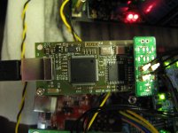
Received the Amanero USB to I2S DSD converter yesterday. I use Ian's BIII adaptor to connect the I2S by u.fl cables. Since the signal is directly connected to BIII without passing through the FIFO and using PC USB power, the SQ is not good. Need to find some improvement method in the related thread.
Attachments
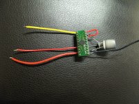
while still waiting for the NTD1 and i570, I've ordered TPS7A4700samples from TI to build the 9V supply for the Arduino and another 5V for the relays. I don't know how to draw PCB layout, so I use a PCB converter and build the PSU easily. This is only a prototype for testing.
Attachments
while still waiting for the NTD1 and i570, I've ordered TPS7A4700samples from TI to build the 9V supply for the Arduino and another 5V for the relays. I don't know how to draw PCB layout, so I use a PCB converter and build the PSU easily. This is only a prototype for testing.
Hi bigpandahk,
Don't use that adapter, it was not designed for a power supply. I'll send you a couple of my TPS7A4700 PCBs for a try.
Ian
- Status
- This old topic is closed. If you want to reopen this topic, contact a moderator using the "Report Post" button.
- Home
- Source & Line
- Digital Line Level
- Build Thread for TPA BIII + Ian Async I2S FIFO + OPC NTD1 + Salas SSLV