The arduino code is easy to use. I refactored the hifiduino into a more object-oriented approach. I kind of made it hardware independant. That is, a volume class is to control volume regardless of which input device is used (apple remote or push button). The underlying device code is just bound in as a library. It made it easier to bind to new controlling devices like , for instance, the DCB1 controller. It also makes it easier to add in new i/o devices. IE: My next step is to control hifiduino through the USB port. I already have the prorotype in a vs2010 project. I merely need to give it a UI and its done.
kind regards.
It will be great if you can share some photos of your project.
posted pics in this thread:
http://www.diyaudio.com/forums/grou...8804-s-pdif-dac-group-buy-44.html#post3145432
http://www.diyaudio.com/forums/grou...8804-s-pdif-dac-group-buy-44.html#post3145432
bigpandahk
I highly recommend using the SD card facility if you want to display images. I had endless trouble until I reverted to the SD card tonight.
great job DQ828, could you provide more details on how to use SD card to store the file?
great job DQ828, could you provide more details on how to use SD card to store the file?
Sure happy to, the code is a work in progress, I have included it so you can see what libraries etc are needed.
Once you have downloaded the libraries #include <tinyFAT.h>
#include <UTFT_tinyFAT.h> I recommend that you should run one of the Demo's in the "example" folder in the UTFT_tinyFAT library.
You will need to get a standard SD card (not a mini or micro) format it to FAT16, How to Format a Fat16 SD Card | eHow.com.
Load the "pic.raw" files into the Root directory of the SD card, the "pic.raw" files are in the "Image-files" folder in the UTFT_tinyFAT library.
In the code you will need to change the "UTFTtf myGLCD(ITDB32S, 38, 39, 40, 41);" to
"UTFTtf myGLCD(ITDB32WD, 38, 39, 40, 41);
I think thats it!
If you want to display your own images, you will need to convert them to the ".RAW" format using Henning Karlsen converter & load them on the SD card. Dont put the files in a folder they need to stay in the Root directory.
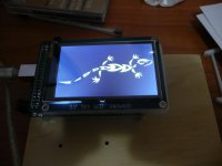
You can see in my code how I got them to display, basically at startup the Lizard displays for a short time, the lizard aslo displays when I turn my system on, I m still working on the rest.
Oh, my courier font doesn't display properly
 still working on that.
With "myGLCD.loadBitmap(0, 48, 400, 144, "L_YGB.RAW");" the 0 & 48 = screen position, the 400 & 144 are the image size, as you can see I have been able to push the width of the image right up to 400 pixels.
Code:
#include <IRremote.h>
#include <IRremoteInt.h>

// CONSTANT DEFINITION

#include <UTFT.h>
#include <tinyFAT.h>
#include <UTFT_tinyFAT.h>

#include <AVR/pgmspace.h>

// Declare which fonts we will be using
extern uint8_t SmallFont[];
extern uint8_t BigFont[];
//extern uint8_t SevenSegNumFont[];
extern uint8_t Courier_24x16[];


UTFTtf myGLCD(ITDB32WD,38,39,40,41);

#define RECV_PIN  12  // IR Receiver pin
#define Relay1       5  // Mains Relay
#define Relay2      11  // Amps Relay
#define Relay3      9  // Cross Over Relay
#define RemoteLED 3  // Remote LED Flashes when Signal Received
#define RECV_Power 13 // To Power IR Reciever using Mega Test Platform

#define ON 1
#define OFF 0

#define CentreButtonCode 2011281932 // Power On & Off
#define MenuButtonCode   2011250700 // Sleep Function, 15min, 30min, 45min & reset
#define UpButtonCode     2011287564 // Volume Up
#define DownButtonCode   2011279372 // Volume Down
#define RightButtonCode  2011291660 // Source selection cycles through 4 inputs

#define potPin A0 // define the analog pin, pin A0 in this case

int val = 0; // variable to store the value coming from the potentiometer
int volumeToDisplay; // variable to store the volume to be displayed


const int motor1Pin = 10;   // H-bridge leg 1 (pin 2, 1A)
const int motor2Pin = 6;    // H-bridge leg 2 (pin 7, 2A)
const int enablePin = 4;    // H-bridge enable pin

int selectionPin1 = 7;    // Selection Pin 1 = B0 or 6 Pin on TP I/O Connector
int selectionPin2 = 8;    // Selection Pin 2 = B1 or 8 Pin on TP I/O Connector


int TurnOffDACXODelay = 2000;  // turn DAC and Xover off after 2 seconds

unsigned long NoSleepDelay = 0;
unsigned long DelayIncrement = 900000;
unsigned long MaxDelay = 2700000;

unsigned long Timer = 0;             // Setting up Timer On
unsigned long MotorRunTime = 700;    // the amount of time we want to run the motor for volume when the button pressed
unsigned long EnablePinTime = 50;    // time after motor turned off that we can disable the pin.
unsigned long LastMotorButton = 0;   // so we know which was the last motor code pressed.

unsigned long DelayRequired = 0;     // current delay selected (or cycled through)
unsigned long TurnOffWhenReached = 0;  // will hold the time at which the Sleep action is initiated.

// Create values for 'storing' states
int centreButtonState;

IRrecv irrecv(RECV_PIN);
decode_results results;

// Setup & Configuration
void setup()
{

  myGLCD.InitLCD();
  myGLCD.clrScr();
  file.initFAT();
  myGLCD.setColor(255,255,255);

  myGLCD.loadBitmap(0, 48, 400, 144, "L_YGB.RAW");

  delay(4000);

  myGLCD.clrScr();

  //Wire.begin();        // Join the I2C bus as a master

    // set all the other pins you're using as outputs:
  pinMode(motor1Pin, OUTPUT);
  pinMode(motor2Pin, OUTPUT);
  pinMode(enablePin, OUTPUT);


  pinMode(RECV_Power, OUTPUT);// To Power IR Reciever using Mega Test Platform

  digitalWrite(RECV_Power, HIGH);// To Power IR Reciever using Mega Test Platform


  // initialize serial communications at 9600 bps:
  Serial.begin(9600);

  irrecv.enableIRIn(); // Start the receiver

  pinMode(Relay1, OUTPUT);  // define Relay1 as an output
  pinMode(Relay2, OUTPUT);
  pinMode(Relay3, OUTPUT);
  pinMode(RemoteLED, OUTPUT);

  pinMode(selectionPin1, OUTPUT);
  pinMode(selectionPin2, OUTPUT);

  TurnOffRelays();
}

void TurnOffRelays() // Turn off the relays including delays
{
  digitalWrite(Relay2, OFF);//Amps Relay
  delay(TurnOffDACXODelay);
  digitalWrite(Relay3, OFF);//Cross Over Relay
  digitalWrite(Relay1, OFF);//Mains Relay==DAC
  DelayRequired = NoSleepDelay;
  TurnOffWhenReached = 0;
  centreButtonState = LOW;    // now make LOW to refelect turned off
}

void FlashLight (int NumbTimes)  // flash the LED light the number of times nominated
{
  for (int i = 1; i<=NumbTimes; i++)
  {
    digitalWrite(RemoteLED, ON);
    delay(250);
    digitalWrite(RemoteLED, OFF);
    if (i < NumbTimes)   // Only want this extra delay if still need to cycle around again.  If on our last time round - don't do it.
      delay(250);
  }
}

void translateIR() // takes action based on IR code received
{
  switch(results.value)
  {
  case CentreButtonCode:
    {
      if(centreButtonState == LOW) {  // if previously LOW
        centreButtonState = HIGH;  // now make HIGH and turn on the relays
        digitalWrite(Relay1, ON);
        digitalWrite(Relay2, ON);
        digitalWrite(Relay3, ON);

        Serial.println("CentreButtonState = HIGH");

        myGLCD.setColor(255,255,255);

        myGLCD.loadBitmap(0, 48, 400, 144, "L_YGB.RAW");

       delay(2000);

        myGLCD.clrScr();

    }
      else  {
        centreButtonState = LOW;    // now make LOW

        Serial.println("CentreButtonState = LOW");
        {
          myGLCD.setFont(Courier_24x16);
          myGLCD.setColor(255, 0, 0);
          myGLCD.print("OFF", CENTER, 80);

          delay(2000);
          myGLCD.clrScr();

          TurnOffRelays();
        }
      }
    }
    break;

  case UpButtonCode:
    {
      if (LastMotorButton != UpButtonCode)  // up botton pressed - make sure we turn off any activity on the down button and setup
      {
        if ( digitalRead(enablePin) == LOW ) {
          digitalWrite(enablePin, HIGH);// Turn on Motor Standby
          Serial.println("UpButtonState - pin set HIGH so motor on standby");
        }
        digitalWrite(motor2Pin, LOW);  // Stop Motor controlling any down button action
        digitalWrite(motor1Pin, HIGH);// Start Motor controlling up button action

        LastMotorButton = UpButtonCode;    // set the variable so know it has been pressed.  If pressed again won't repeat these action.
        Serial.println("UpButtonState - motor2 LOW and off, motor1 HIGH and started");
      }
      Timer = millis();


      Serial.println("UpButtonState - Timer reset to now");
    }
    break;

  case DownButtonCode:
    {
      if (LastMotorButton != DownButtonCode)  // down botton pressed after another button - make sure we turn off any activity on the up button and setup
      {
        if ( digitalRead(enablePin) == LOW ) { // which means the enablePin will have been reset to LOW - so set to HIGH here
          digitalWrite(enablePin, HIGH);// Turn on Motor Standby
          Serial.println("DownButtonState - pin set HIGH so motor on standby");
        }
        digitalWrite(motor1Pin, LOW);  // Stop Motor controlling any up button action
        digitalWrite(motor2Pin, HIGH);// Start Motor controlling down button action

        LastMotorButton = DownButtonCode;    // set the variable so know it has been pressed.  If pressed again won't repeat these action.
        Serial.println("DownButtonState - motor1 LOW and off, motor2 HIGH and started");
      }
      Timer = millis();
      Serial.println("DownButtonState - Timer reset to now");
    }
    break;


   case RightButtonCode:

    {
      if (digitalRead(selectionPin1) == LOW && digitalRead(selectionPin2) == LOW)
      {
        digitalWrite(selectionPin1, HIGH);// BO on TP DAC Terminal Pin 7 on Mega
        digitalWrite(selectionPin2, HIGH);// B1 on TP DAC Terminal Pin 8 on Mega
        myGLCD.setFont(BigFont);
        myGLCD.setColor(255, 255, 0);
        myGLCD.print("Source 1", RIGHT, 10);
        Serial.println("Source 1");
        FlashLight(1);
      }

      else if (digitalRead(selectionPin1) == HIGH && digitalRead(selectionPin2) == HIGH)
      {
        digitalWrite(selectionPin1, LOW);// BO on TP DAC Terminal Pin 7 on Mega
        myGLCD.setFont(BigFont);
        myGLCD.setColor(255, 255, 0);
        myGLCD.print("Source 2", RIGHT, 10);
        Serial.println("Source 2");
        FlashLight(2);
      }

      else if (digitalRead(selectionPin1) == LOW && digitalRead(selectionPin2) == HIGH) //
      {
        digitalWrite(selectionPin1, HIGH);// BO on TP DAC Terminal Pin 7 on Mega
        digitalWrite(selectionPin2, LOW);// B1 on TP DAC Terminal Pin 8 on Mega
        myGLCD.setFont(BigFont);
        myGLCD.setColor(255, 255, 0);
        myGLCD.print("Source 3", RIGHT, 10);
        Serial.println("Source 3");
        FlashLight(3);
      }

      else if (digitalRead(selectionPin1) == HIGH && digitalRead(selectionPin2) == LOW) // Iv'e done this line differently to the one above :)
      {
        digitalWrite(selectionPin1, LOW);// BO on TP DAC Terminal Pin 7 on Mega
        myGLCD.setFont(BigFont);
        myGLCD.setColor(255, 255, 0);
        myGLCD.print("Squeezebox", RIGHT, 10);
        Serial.println("Source 4");
        FlashLight(4);
      }
    }

    break;


  case MenuButtonCode:
    {

      if (DelayRequired == MaxDelay) {           // Have cycled back to the "No delay" state
        FlashLight(2);
        DelayRequired = NoSleepDelay;
        TurnOffWhenReached = 0;
        myGLCD.setFont(BigFont);
        myGLCD.setColor(255, 255, 0);
        myGLCD.print("SLEEP OFF", CENTER, 100);
        delay(2000);
        myGLCD.clrScr();
      }
      else  {                // A delay is required
        FlashLight(1);
        DelayRequired = DelayRequired + DelayIncrement;   // incement our delay value up by the increment value
        TurnOffWhenReached = DelayRequired + millis();    // Set the time when we want to shut down the relays.
      }
    }  //end case
    break;
  }  // end switch
}    // end function

// Main Loop
void loop(){

  /*{
    val = analogRead(potPin); // read the value from the sensor
    volumeToDisplay = (val / 10); // calculate the volume
  }*/

  {
    if (irrecv.decode(&results)) // have we received an IR signal?

    {
      translateIR();
      irrecv.resume(); // receive the next value
    }

    if (DelayRequired != NoSleepDelay && millis() > TurnOffWhenReached) {  // check that a standby setting has been chosen and that we are past the time when we want it turned off.
      TurnOffRelays();
    }

    if (LastMotorButton != 0 && millis()-Timer >= MotorRunTime) {  // the Up or Down buttons have been pressed and the current time is now past our motorRunTime setting
      if (LastMotorButton == UpButtonCode) {
        digitalWrite(motor1Pin, LOW);  // Stop Motor associated with Up button
        Serial.println("in Loop, timer has run out, UpButtonState last one so motor1pin turned off");
      }
      else {
        digitalWrite(motor2Pin, LOW);  // Stothp Motor associated with Down button
        Serial.println("in Loop, timer has run out, DownButtonState last one so motor2pin turned off");
      }
      LastMotorButton = 0;  // reset to indicate all up/down button actions have finished for the moment
    }

    if (LastMotorButton == 0 && millis()-Timer >= MotorRunTime + EnablePinTime && digitalRead(enablePin) == HIGH){ // have tunred off motors, time has passed and pin still on
      digitalWrite(enablePin, LOW);  // Turn off enablePin
      Serial.println("in Loop, timer for the enable Pin has run out so enablepin turned off");
    }
  }
}
Last edited:
WARNING WARNING Will Robinson, keep the file names SHORT, I just wasted hours trying to get other images to load, when my brain finally coughed up something I had read days ago "keep the file names short" I didn't realise how short.
Thanks DQ828
Just received the new BIII and is busy to carefully check everything and wiring before power it up. Will try the bitmap display with your suggestion later.
Thanks DQ828
Just received the new BIII and is busy to carefully check everything and wiring before power it up. Will try the bitmap display with your suggestion later.
Good luck I have my fingers crossed.
Received the new BIII yesterday and took an hour to solder all the connectors and jumpers. Then test it with the Bench PSU, 5.2V @ 460mA constantly, with all LEDs on Tridents and "Mute" on.
Use resistor to load the SSLV and confirmed it is working perfectly. Following the Legato setup procedures and adjust all the VRs. Then put the BIII onto the Legato and power ON.
The LEDs on the tridents slightly blinking, check the 5.25V power and it drops to 4.6XV, something shorted Switch off the power immediately, remove the BIII from Legato, power up and voltage back to normal 5.25.
Something on Legato overload the BIII. Check all the bipolars and FETs are fine. Seems the output buffer IC LME49600 has lower resistance to GND. I have no way to confirm whether it is dead. Have to order two new IC and replace them.
Use resistor to load the SSLV and confirmed it is working perfectly. Following the Legato setup procedures and adjust all the VRs. Then put the BIII onto the Legato and power ON.
The LEDs on the tridents slightly blinking, check the 5.25V power and it drops to 4.6XV, something shorted
Switch off the power immediately, remove the BIII from Legato, power up and voltage back to normal 5.25.Something on Legato overload the BIII. Check all the bipolars and FETs are fine. Seems the output buffer IC LME49600 has lower resistance to GND. I have no way to confirm whether it is dead. Have to order two new IC and replace them.

so you scraped off some soldermask yeah? cant quite see if you have, they really need at least one of the grounds soldered properly or they just rip off first time you unplug the cable
Yes Qusp, it took me most of the time to scraped off the soldermask at both sides of the sockets.
The buffer IC arrived yesterday and I replaced them last night, problem still exists, everything were fine before I put the BIII onto the Legato, but the 5.25V to BIII dropped to 4.6V when with the Legato.
Before I burnt the BIII, I re-installed the three SSLV with individual heatsink into the case with comment heatsink. I didn't realize any problem when measure the output of individual power supply.
Spent almost two hours, finally found two problems (actually they are the same). Both the -15V and the +5.25V have one insulation pad didn't perform their job. The GND of -15V and the POS of +5.25V shorted to the heat sinks. When putting the BIII onto the Legato and have the common GND, the +5.25V will become +20V with reference to the GND on Legato, this may be the reason for the burnt BIII.
I don't know whether the new BIII is still alive or not although ALL LEDs function properly. Still no sound from the Legato I haven't installed the jumpers for PCM input and will install them tonight.
Before I burnt the BIII, I re-installed the three SSLV with individual heatsink into the case with comment heatsink. I didn't realize any problem when measure the output of individual power supply.
Spent almost two hours, finally found two problems (actually they are the same). Both the -15V and the +5.25V have one insulation pad didn't perform their job. The GND of -15V and the POS of +5.25V shorted to the heat sinks. When putting the BIII onto the Legato and have the common GND, the +5.25V will become +20V with reference to the GND on Legato, this may be the reason for the burnt BIII.
I don't know whether the new BIII is still alive or not although ALL LEDs function properly. Still no sound from the Legato
I haven't installed the jumpers for PCM input and will install them tonight.Glad you found the problem finally. Hope everything is fine
Ian
Thanks Ian
Hope there will be music output from BIII after I add the jumpers. Will try to repair the burnt BIII again and your new i570 clock board with dual I2S output will be a perfect match for my Dual Mono config.
The buffer IC arrived yesterday and I replaced them last night, problem still exists, everything were fine before I put the BIII onto the Legato, but the 5.25V to BIII dropped to 4.6V when with the Legato.
Before I burnt the BIII, I re-installed the three SSLV with individual heatsink into the case with comment heatsink. I didn't realize any problem when measure the output of individual power supply.
Spent almost two hours, finally found two problems (actually they are the same). Both the -15V and the +5.25V have one insulation pad didn't perform their job. The GND of -15V and the POS of +5.25V shorted to the heat sinks. When putting the BIII onto the Legato and have the common GND, the +5.25V will become +20V with reference to the GND on Legato, this may be the reason for the burnt BIII.
I don't know whether the new BIII is still alive or not although ALL LEDs function properly. Still no sound from the Legato
Also glad to hear you found the problem. It was really strange why an output stage would kill the chip, Hope the DAC survived the voltage stress.
Sure happy to, the code is a work in progress, I have included it so you can see what libraries etc are needed.
Once you have downloaded the libraries #include <tinyFAT.h>
#include <UTFT_tinyFAT.h> I recommend that you should run one of the Demo's in the "example" folder in the UTFT_tinyFAT library.
You will need to get a standard SD card (not a mini or micro) format it to FAT16, How to Format a Fat16 SD Card | eHow.com.
Load the "pic.raw" files into the Root directory of the SD card, the "pic.raw" files are in the "Image-files" folder in the UTFT_tinyFAT library.
In the code you will need to change the "UTFTtf myGLCD(ITDB32S, 38, 39, 40, 41);" to
"UTFTtf myGLCD(ITDB32WD, 38, 39, 40, 41);
I think thats it!
If you want to display your own images, you will need to convert them to the ".RAW" format using Henning Karlsen converter & load them on the SD card. Dont put the files in a folder they need to stay in the Root directory.
You can see in my code how I got them to display, basically at startup the Lizard displays for a short time, the lizard aslo displays when I turn my system on, I m still working on the rest.
Oh, my courier font doesn't display properly
With "myGLCD.loadBitmap(0, 48, 400, 144, "L_YGB.RAW");" the 0 & 48 = screen position, the 400 & 144 are the image size, as you can see I have been able to push the width of the image right up to 400 pixels.
I have no problem on converting the bitmap to RAW and loaded it into the SD, compiled without error but can't display the bitmap. don't know whether there is problem on converting the file. Can I have your RAW file for testing?
Last edited:
I soldered the three jumpers for PCM input. Connect the Arduino to BIII via I2C. The response to the volume control and display of parameters are much slower than normal. Frequency display also higher than actual. No sound output from Legato. Can anyone advise what should I do to find the problem?
I soldered the three jumpers for PCM input. Connect the Arduino to BIII via I2C. The response to the volume control and display of parameters are much slower than normal. Frequency display also higher than actual. No sound output from Legato. Can anyone advise what should I do to find the problem?
1- Remove Legato. Connect direct to amp or preamp
2- Reinstall original firmware chip (this will give you full volume, but can reduce the volume in the computer if you are using USB output - or else use a preamp)
- Status
- This old topic is closed. If you want to reopen this topic, contact a moderator using the "Report Post" button.
- Home
- Source & Line
- Digital Line Level
- Build Thread for TPA BIII + Ian Async I2S FIFO + OPC NTD1 + Salas SSLV