I'm sure you'll become an expert after you fix your BIII.
Ian
I learnt a lot from experts here (of course including you, Ian)
but also paid a lot This is my first time handling SMT devices. Remove the chip is easy but putting the new chip onto the board should be a lot difficult
Practice make perfect. I like to use a lot of flux when doing SMD, especially 'spider' IC, a magnifier and small flat tips soldering iron help a lot. Search for the technique in YouTube. It is fun.
Yes, finding some video from youtube would be help.
Keep the old solder paste on pads, try this one: SMD29130CC Chip Quik Inc | SMD29130CC-ND | DigiKey
place your new chip exactly on position, with a little metal piece pressed on top, then your SMT station. I'm sure it will be perfect job.
Ian
Coolhead
Thanks very much for your advice.
Ian
I've bought the Chip Quik as per your suggestion. The chip will be delivered tomorrow and hope I have good news to tell.
After you put in the new chip, make sure you check the pins if the short is still there before power on.
After you put in the new chip, make sure you check the pins if the short is still there before power on.
Yes Sir
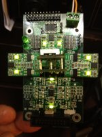
Received the chip today and put it onto the PCB. To align all the pins is not a easy task. A little press will move it away. I finally use the soldiering iron to fix two pins then use the SMT station. The hot air blowed away one of the capacitor on the PCB and I can't find it.
Measure the resistance between DVCC and GND, > 1.2Kohm. everything seems fine.
Put back all the tridents, connect it to the bench PSU. Power up, all LEDs on including the "Mute". Current is around 650mA.
But after a few seconds, the "Mute" LED off and occasionally flash. I measure the output voltages of the tridents, both DVCC and VDD output are below 0.4V.
Seems something still short.
Attachments
You should pull out tridents and separate test it out with separate 5v power supply. You should test out other modules also, it could be more problem. You could be un-doing all the hardworking without testing out every module, 1 faulty module could create the same chain reaction.Received the chip today and put it onto the PCB. To align all the pins is not a easy task. A little press will move it away. I finally use the soldiering iron to fix two pins then use the SMT station. The hot air blowed away one of the capacitor on the PCB and I can't find it.
Measure the resistance between DVCC and GND, > 1.2Kohm. everything seems fine.
Put back all the tridents, connect it to the bench PSU. Power up, all LEDs on including the "Mute". Current is around 650mA.
But after a few seconds, the "Mute" LED off and occasionally flash. I measure the output voltages of the tridents, both DVCC and VDD output are below 0.4V.
Seems something still short.
You should pull out tridents and separate test it out with separate 5v power supply. You should test out other modules also, it could be more problem. You could be un-doing all the hardworking without testing out every module, 1 faulty module could create the same chain reaction.
I've tested all the tridents before put it back to the BIII. I don't know the way forward, whether buy a new BIII or spend more time and money to trouble shoot the BIII
I have no idea how Ian's adapter is designed and if it automatically disables the onboard power for the clock, One of the Tridents feeds the onboard clock crystal. If you are feeding an external masterclock signal I would expect that the Trident and supply to the onboard crystal needs to be disconnected. Hope this helps.
David
David
Last edited:
I have no idea how Ian's adapter is designed and if it automatically disables the onboard power for the clock, One of the Tridents feeds the onboard clock crystal. If you are feeding an external masterclock signal I would expect that the Trident and supply to the onboard crystal needs to be disconnected. Hope this helps.
David
Ian's adaptor is simply remove the crystal if external clock is used. The Trident output just open and connected to nothing.
The BIII should not be so easy be killed. Glad that you can still enjoy music from BIII. I may have to buy a new one
I removed all the tridents from the BIII, check each of them using a bench PSU and a VR as dummy load. None of them have problem. Then I used the bench PSU to power each sections of BIII, set the current limited to 100mA which is the current limit of trident. Both DVCC and VDD caused the PSU overloaded. I checked the circuit board and data sheet, the only thing loads these two supplies is the ES9018 chip. To confirm this, I remove the chip from the PCB again. Then apply voltage to both pins again, both pins are opened circuit and drawn no current. This further confirmed again the chip failed. Did I damage the chip during the soldering? Or bought a fake chip from China? Never know!!
I checked all the tridents and the PCB again and again but found nothing that may cause the damage to the chip. I couldn't think of any other diagnostic to be done. So I ordered another chip and put it back to the BIII. I use the multi-meter to confirm no short, then use the bench PSU to power each sections one by one and confirmed no overload. Everything seems better this time. Finally I put back all the tridents and power the BIII by the bench PSU. Total current drawn is 650mA, all LEDs on tridents "On" steadily. The Mute LED also ON. Up to this stage, everything normal on the BIII except the capacitor C17 is missing which was blown away by the hot gun and I couldn't find it.
Will connect it to the FIFO tonight and hope everything goes fine.
I removed all the tridents from the BIII, check each of them using a bench PSU and a VR as dummy load. None of them have problem. Then I used the bench PSU to power each sections of BIII, set the current limited to 100mA which is the current limit of trident. Both DVCC and VDD caused the PSU overloaded. I checked the circuit board and data sheet, the only thing loads these two supplies is the ES9018 chip. To confirm this, I remove the chip from the PCB again. Then apply voltage to both pins again, both pins are opened circuit and drawn no current. This further confirmed again the chip failed. Did I damage the chip during the soldering? Or bought a fake chip from China? Never know!!
I checked all the tridents and the PCB again and again but found nothing that may cause the damage to the chip. I couldn't think of any other diagnostic to be done. So I ordered another chip and put it back to the BIII. I use the multi-meter to confirm no short, then use the bench PSU to power each sections one by one and confirmed no overload. Everything seems better this time. Finally I put back all the tridents and power the BIII by the bench PSU. Total current drawn is 650mA, all LEDs on tridents "On" steadily. The Mute LED also ON. Up to this stage, everything normal on the BIII except the capacitor C17 is missing which was blown away by the hot gun and I couldn't find it.
Will connect it to the FIFO tonight and hope everything goes fine.
Good luck my fingers are crossed.
I removed all the tridents from the BIII, check each of them using a bench PSU and a VR as dummy load. None of them have problem. Then I used the bench PSU to power each sections of BIII, set the current limited to 100mA which is the current limit of trident. Both DVCC and VDD caused the PSU overloaded. I checked the circuit board and data sheet, the only thing loads these two supplies is the ES9018 chip. To confirm this, I remove the chip from the PCB again. Then apply voltage to both pins again, both pins are opened circuit and drawn no current. This further confirmed again the chip failed. Did I damage the chip during the soldering? Or bought a fake chip from China? Never know!!
I checked all the tridents and the PCB again and again but found nothing that may cause the damage to the chip. I couldn't think of any other diagnostic to be done. So I ordered another chip and put it back to the BIII. I use the multi-meter to confirm no short, then use the bench PSU to power each sections one by one and confirmed no overload. Everything seems better this time. Finally I put back all the tridents and power the BIII by the bench PSU. Total current drawn is 650mA, all LEDs on tridents "On" steadily. The Mute LED also ON. Up to this stage, everything normal on the BIII except the capacitor C17 is missing which was blown away by the hot gun and I couldn't find it.
Will connect it to the FIFO tonight and hope everything goes fine.
Good to know you make it
. Enjoy your project.Ian
Thanks DQ828 and Ian, but I didn't make it
The BIII behaved OK when I tested it with the bench PSU. Then I put it back onto the legato and connected the FIFO. Before that I checked all the output of the SSLV. Then power up, within seconds, the LED on the tridents blinking. Then I knew the same thing happened again. DVCC shorted to GND.
Since there are only two ICs and one regulator on the BIII other than those passive components. The DVCC only connected to the ES9018. I can't think of any other source that kill the BIII and the only suspect is the legato. Will check tonight.
Already lost one third of a new BIII
- Status
- This old topic is closed. If you want to reopen this topic, contact a moderator using the "Report Post" button.
- Home
- Source & Line
- Digital Line Level
- Build Thread for TPA BIII + Ian Async I2S FIFO + OPC NTD1 + Salas SSLV