I'll set up a Google Docs for files so they can be saved for future access.
I'm working on a spreadsheet with current demand of the chips for comparison to actual current demand.
I powered mine up today and was not disappointed.
I think the designer actually did a pretty good job on it with relatively few areas for improvement (other than changing to better components). The SOT233 regulators are not low noise and the data sheet shows them designed for use in SCSI termination, Battery Chargers, etc. However, the use of 78/79xx pre-regulators eliminates a lot of power supply noise.
Last edited:
Someone let me know if this link works. It should show 3 files, the top and bottom pictures and the schematic.
https://docs.google.com/#owned-by-me
https://docs.google.com/#owned-by-me
Nope, not good. the link as it is, it requires to sign on and then sends me to my documents.
As for the 1000uF instead of 100uF on output of regs - the bass sounds like it should be on my headphones. Maybe for line level 100uF was OK, but for headphones definitely was needed more storage.
As for the 1000uF instead of 100uF on output of regs - the bass sounds like it should be on my headphones. Maybe for line level 100uF was OK, but for headphones definitely was needed more storage.
I guess I need to read some docs to figure out how it works.
https://docs.google.com/file/d/0B6gNt_1vMtJVUVJMNGhUX3VSUzQ/edit
Lets see if this works.
By the way,
How do we go about measuring the performance of a DAC?
Wave files will play 44.1K through media player. But how to get 96KHz output from a windows pc?
I've got AudioTester which will go to 192Ks/s, but it uses the sound card for both input and output. I can measure the output of the DAC feed into the audio card with AudioTester, but it won't drive the USB output.
That works.
I measure mine with my soundcard: E-MU1820m.
I don't have the auxiliary digital I/O and via PCI coax it cannot output 192kHz (only on ADAT). It has ballanced inputs so I have to short one of the sides to ground to input unballanced signals.
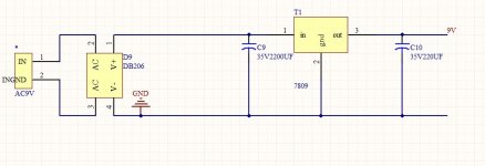
You can add those files. First two are from Lisa (ljm).
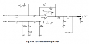
Last one is the recomended analog out stage from datasheet.
I measure mine with my soundcard: E-MU1820m.
I don't have the auxiliary digital I/O and via PCI coax it cannot output 192kHz (only on ADAT). It has ballanced inputs so I have to short one of the sides to ground to input unballanced signals.
You can add those files. First two are from Lisa (ljm).
Last one is the recomended analog out stage from datasheet.
Attachments
Last edited:
I've got the M-Audio Audiophile 192 which does support SPDIF so I should be able to test that.
MY issue is when testing USB input. What do I need under windows (XP-Pro) to drive it with to get a 92K sample rate source out of the USB port. And, what to use as the file for testing? Do I need to record test tones with the sound card set for 96K sample rate, and play them back via USB?
M-AUDIO - Audiophile 192 - High-Definition 4-In/4-Out Audio Card with Digital I/O and MIDI
I'm using AuidioTester, which supports up to 192K sample rate, but does not seem to support USB.
audioTester
Thanks for the additional data, I'll upload the files tonight. I can't access Docs from work.
I just looked at the Audio Tester site, and it looks like the latest release supports USB devices. I'll have to download the release and try it.
If that works, I only need to get some high sample rate music for testing with.
Last edited:
Oops, yup on the transfer rate. CD is 44.1 and windows is 48 (thank you Bill Gates for another standard). The chip doc does not specify sample rate, only USB 1.0 compliant. I assumed wrong (Assume Makes an A** out of You and Me).
I'm still trying to get used to all the specifics and get up to speed.
Ok. I uploaded all three documents at once, but it only set the first to share. All three should be share now.
If I'm playing windows media player and it shows 256Kb/s (which doesn't make sense at all), what is the bit transfer rate?
I'm running a WM8741 with a TI PCM2707 and SRC4192.
I installed the latest version of AudioTester and it does support a USB DAC now, so I should be good for testing with SPDIF (except I left the DAC at work and can't test it, hence the fallback to theWM8741).
TKS SoNic_real_one.
I downloaded it and got it working. I need to do some studying and probably download a few addons.
Mean time I got the board working in both USB and SPDIF. I was testing frequency response in SPDIF with AudoTester when it dawned on me that I was wasting time. All three modes track identically out to 22.05KHz (as they should unless different digital filters are used, with cutoff below the analog filter cutoff).
It is illogical to attempt to output a frequency higher than 22.05KHz in 44.1Ks/s mode.
The response to 96Ks/s and 192Ks/s are slightly different beyond the filter -3dB point, but that could be due to the internal digital filters.
So, I'm going to burn it in a while and take a hiatus and work on getting my bike back together. It has been sitting for two years and I need the shelf space the parts are taking up.
My DAC finally arrived so here is an x-ray view of the board;
http://www.pohrani.com/f/2g/v2/33hqIbEV/pcbdac.jpg
should make life easier for some...")
http://www.pohrani.com/f/2g/v2/33hqIbEV/pcbdac.jpg
should make life easier for some...
Accumulated wisdom a few months on?
Hi,
I've just received the kit for one of these DACs and have been reading this thread. It's been dormant a few months now so I'm wondering what the collective wisdom/conclusions are for any tweaks that I can try with the DAC.
Ultimately I hope to drive it over USB from my Raspberry Pi but for the minute I'll experiment with a Windows laptop. I also have a DAB tuner with SPDIF out (I think) so I can play with that too.
Thanks,
Andy.
A modification...
Well, like dozens of other "made in china" DAC it all comes down to two things, upgrading the power supply and upgrading the output stage...
Changing the existing components with better/more expensive ones will only get you so far. The next bigger modification would be to change the
complete power supply section and output stage. However not everyone has enough knowledge/experience to try something more complicated, non
the less, for those willing to try here is a short tutorial;
First thing on the list;
remove everything from the board except CS8416 & CS4398.
Just to mention, if you remove the HEX inverter (74HC04) you will lose
all LED indication, mess up CS8416 input select and reset circuit...
How to connect input select & reset circuit will be explained later in the text.
This DAC was made with only one goal - to play music over SPDIF the best it can...
*****************************************************************************************************
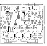
Now to fill the board with the necessary parts, which components
to put on the board you can see on the picture below;
As for choice of components; for the PLL circuit (223, 102 caps and 3k resistor) left of
CS8416, it would be good to use C0G and X7R ceramic capacitors and 1% metalfilm resistor.
I also put X7R ceramic capacitors for chip decoupling together with electrolytic caps
in parallel on the bottom side of the board...
Just avoid large "exotic" capacitors with long leads and you can't go wrong...
*****************************************************************************************************
Next part, separating the CS8416 & CS4398 digital parts, and
preparation for the new regulators, reset circuit and input select.
From the picture below - cut the red lines and connect the green ones.
The yellow one is input select, so you can also connect it to GND
as on the picture...
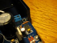
For the reset circuit I used TPS3809 from Farnell (1103116 - TPS3809K33DBVT), it's reeeeeally small and pain in the a$$ to solder, but not impossible...
The little bugger soldered;
The reset chip has 3 pins, it should be clear where to connect/solder each pin, so I won't go into details...
*****************************************************************************************************
And finally, the new regulators.
I used LT1763 low noise regulators, available on ebay, Farnell etc. - not hard to get, and a lot better than that crappy AMS1117...
The pcb;
Here is the PCB in .LAY format (Sprint Layout) - http://dl.dropbox.com/u/17898498/upload/LT1763_REG.LAY
The BOM from Farnell;
1273614 - LINEAR TECHNOLOGY - LT1763CS8#PBF - V REG, LDO ADJ, SMD, SOIC8, 1763
2118134 - KEMET - C1206C106K3RAC TU - CAPACITOR, 10UF, 25V, X7R, 1206
8820155 - MURATA - GRM3195C1H103JA01D - CAPACITOR, 1206, 10NF, 50V
9333363 - MULTICOMP - MC 0.1W 0805 1% 560R - RESISTOR, 0805 560R
9333037 - MULTICOMP - MC 0.1W 0805 1% 330R - RESISTOR, 0805 330R
9332383 - MULTICOMP - MC 0.1W 0805 1% 1K - RESISTOR, 0805 1K,0.1W,1%
However you can get LT1763 at a lower price on ebay...
The finished PCB;
And the new regulators connected to the PCB;
Once again, the picture is pretty much self-explanatory, so I won't write
too much because this post would be waaaay too long, but if anything so far is unclear - questions are welcome...
*****************************************************************************************************
And the last part - the preregulators;
The choice has fallen on simple shunt regulators with TL431 & BD140...
Here is the schematic:
The PCB:
And the files;
Sprint Layout PCB - http://dl.dropbox.com/u/17898498/upload/SHUNT_REG2.LAY - 4 shunts on one board...
Circuit in Multisim - http://dl.dropbox.com/u/17898498/upload/psu_prereg.ms11
The resistors in CRC filter are soldered under the board, to the pins of the capacitors...
The BOM from Farnell;
2063072 - PANASONIC - EEUFR1E122L - CAPACITOR, RADIAL, 25V, 1200UF, 20%
1565261 - WELWYN - W31-5R6JI - RESISTOR, 3W 5% 5R6
1324152 - MULTICOMP - 1N4007G - DIODE, STANDARD, 1A, 1000V
1216440 - MULTICOMP - MCRR50104X7RK0050 - CAPACITOR, 100NF, 50V
1219468 - PANASONIC - EEUFM1E221 - CAPACITOR, RADIAL, 220UF, 25V
1848455 - PANASONIC - EEUFC1H1R0 - CAPACITOR, RADIAL, 50V, 1UF
9692495 - PANASONIC - EEUFC1J220 - CAPACITOR, 22UF, 63V
1565225 - WELWYN - W31-12RJI - RESISTOR, 3W 5% 12R
1084566 - STMICROELECTRONICS - BD140-16 - TRANSISTOR, PNP, SOT-32
9593543 - TEXAS INSTRUMENTS - TL431ACLP - SHUNT REG ADJ +2.5/36V, TO-92, 431
9558489 - ON SEMICONDUCTOR - BC327-25ZL1G - TRANSISTOR, PNP, TO-92
9341099 - MULTICOMP - MF25 100R - RESISTOR, 0.25W 1% 100R
9341102 - MULTICOMP - MF25 1K - RESISTOR, 0.25W 1% 1K
9341439 - MULTICOMP - MF25 1K8 - RESISTOR, 0.25W 1% 1K8
Sorry, don't have the exact quantity of each component...
*****************************************************************************************************
And the finished DAC in testing phase;
For the output stage I used Tamura TFP-3W transformers - caught for a fair price on ebay...
I just don't like the sound of opamps - it's a personal preference - I tried a bunch of them,
some pretty expensive, all sort of power supplys, but none came close to the natural sound of the transformers...
The sound of this modified DAC is incomparable to the "stock" one - the 3D stage,
depth, details, dynamics... I was stunned with the sound when this little DAC started playing.
Before the comments start, I know it's not perfect and could be improved, but this was
made for a friend and I tried to keep the cost of the build on a reasonable level.
The shunt regulators are probably the first thing that could be improved, it's my first
time trying to make something like this, but it works great and the price of parts is acceptable.
If anyone wants to try and build this, I'll help as much as I can, so
questions are welcome...
Well, like dozens of other "made in china" DAC it all comes down to two things, upgrading the power supply and upgrading the output stage...
Changing the existing components with better/more expensive ones will only get you so far. The next bigger modification would be to change the
complete power supply section and output stage. However not everyone has enough knowledge/experience to try something more complicated, non
the less, for those willing to try here is a short tutorial;
First thing on the list;
remove everything from the board except CS8416 & CS4398.
An externally hosted image should be here but it was not working when we last tested it.
Just to mention, if you remove the HEX inverter (74HC04) you will lose
all LED indication, mess up CS8416 input select and reset circuit...
How to connect input select & reset circuit will be explained later in the text.
This DAC was made with only one goal - to play music over SPDIF the best it can...
*****************************************************************************************************
Now to fill the board with the necessary parts, which components
to put on the board you can see on the picture below;
An externally hosted image should be here but it was not working when we last tested it.
As for choice of components; for the PLL circuit (223, 102 caps and 3k resistor) left of
CS8416, it would be good to use C0G and X7R ceramic capacitors and 1% metalfilm resistor.
I also put X7R ceramic capacitors for chip decoupling together with electrolytic caps
in parallel on the bottom side of the board...
Just avoid large "exotic" capacitors with long leads and you can't go wrong...
*****************************************************************************************************
Next part, separating the CS8416 & CS4398 digital parts, and
preparation for the new regulators, reset circuit and input select.
From the picture below - cut the red lines and connect the green ones.
The yellow one is input select, so you can also connect it to GND
as on the picture...
An externally hosted image should be here but it was not working when we last tested it.
For the reset circuit I used TPS3809 from Farnell (1103116 - TPS3809K33DBVT), it's reeeeeally small and pain in the a$$ to solder, but not impossible...
The little bugger soldered;
An externally hosted image should be here but it was not working when we last tested it.
The reset chip has 3 pins, it should be clear where to connect/solder each pin, so I won't go into details...
*****************************************************************************************************
And finally, the new regulators.
I used LT1763 low noise regulators, available on ebay, Farnell etc. - not hard to get, and a lot better than that crappy AMS1117...
The pcb;
An externally hosted image should be here but it was not working when we last tested it.
Here is the PCB in .LAY format (Sprint Layout) - http://dl.dropbox.com/u/17898498/upload/LT1763_REG.LAY
The BOM from Farnell;
1273614 - LINEAR TECHNOLOGY - LT1763CS8#PBF - V REG, LDO ADJ, SMD, SOIC8, 1763
2118134 - KEMET - C1206C106K3RAC TU - CAPACITOR, 10UF, 25V, X7R, 1206
8820155 - MURATA - GRM3195C1H103JA01D - CAPACITOR, 1206, 10NF, 50V
9333363 - MULTICOMP - MC 0.1W 0805 1% 560R - RESISTOR, 0805 560R
9333037 - MULTICOMP - MC 0.1W 0805 1% 330R - RESISTOR, 0805 330R
9332383 - MULTICOMP - MC 0.1W 0805 1% 1K - RESISTOR, 0805 1K,0.1W,1%
However you can get LT1763 at a lower price on ebay...
The finished PCB;
An externally hosted image should be here but it was not working when we last tested it.
And the new regulators connected to the PCB;
An externally hosted image should be here but it was not working when we last tested it.
Once again, the picture is pretty much self-explanatory, so I won't write
too much because this post would be waaaay too long, but if anything so far is unclear - questions are welcome...
*****************************************************************************************************
And the last part - the preregulators;
The choice has fallen on simple shunt regulators with TL431 & BD140...
Here is the schematic:
An externally hosted image should be here but it was not working when we last tested it.
The PCB:
An externally hosted image should be here but it was not working when we last tested it.
And the files;
Sprint Layout PCB - http://dl.dropbox.com/u/17898498/upload/SHUNT_REG2.LAY - 4 shunts on one board...
Circuit in Multisim - http://dl.dropbox.com/u/17898498/upload/psu_prereg.ms11
The resistors in CRC filter are soldered under the board, to the pins of the capacitors...
The BOM from Farnell;
2063072 - PANASONIC - EEUFR1E122L - CAPACITOR, RADIAL, 25V, 1200UF, 20%
1565261 - WELWYN - W31-5R6JI - RESISTOR, 3W 5% 5R6
1324152 - MULTICOMP - 1N4007G - DIODE, STANDARD, 1A, 1000V
1216440 - MULTICOMP - MCRR50104X7RK0050 - CAPACITOR, 100NF, 50V
1219468 - PANASONIC - EEUFM1E221 - CAPACITOR, RADIAL, 220UF, 25V
1848455 - PANASONIC - EEUFC1H1R0 - CAPACITOR, RADIAL, 50V, 1UF
9692495 - PANASONIC - EEUFC1J220 - CAPACITOR, 22UF, 63V
1565225 - WELWYN - W31-12RJI - RESISTOR, 3W 5% 12R
1084566 - STMICROELECTRONICS - BD140-16 - TRANSISTOR, PNP, SOT-32
9593543 - TEXAS INSTRUMENTS - TL431ACLP - SHUNT REG ADJ +2.5/36V, TO-92, 431
9558489 - ON SEMICONDUCTOR - BC327-25ZL1G - TRANSISTOR, PNP, TO-92
9341099 - MULTICOMP - MF25 100R - RESISTOR, 0.25W 1% 100R
9341102 - MULTICOMP - MF25 1K - RESISTOR, 0.25W 1% 1K
9341439 - MULTICOMP - MF25 1K8 - RESISTOR, 0.25W 1% 1K8
Sorry, don't have the exact quantity of each component...
*****************************************************************************************************
And the finished DAC in testing phase;
An externally hosted image should be here but it was not working when we last tested it.
For the output stage I used Tamura TFP-3W transformers - caught for a fair price on ebay...
I just don't like the sound of opamps - it's a personal preference - I tried a bunch of them,
some pretty expensive, all sort of power supplys, but none came close to the natural sound of the transformers...
The sound of this modified DAC is incomparable to the "stock" one - the 3D stage,
depth, details, dynamics... I was stunned with the sound when this little DAC started playing.
Before the comments start, I know it's not perfect and could be improved, but this was
made for a friend and I tried to keep the cost of the build on a reasonable level.
The shunt regulators are probably the first thing that could be improved, it's my first
time trying to make something like this, but it works great and the price of parts is acceptable.
If anyone wants to try and build this, I'll help as much as I can, so
questions are welcome...
Wow, that's a bit more than just an upgrade Ch33ta! However, I have a basic problem; I've assembled the board and it doesn't work - I hear just (quiet) noise through my hi-fi! I am powering it from a transformer that has two 15V outputs and two 9V outputs. Nothing has blown up, the LEDs all light (even the one labelled 'locked') appropriately (i.e. the USB one lights when I connect a computer to the DAC via USB). Strangely the OpAmp seems to have been dead on arrival as I tried it in my phono pre-amp and that ceased to work. I've swapped one from my working phono pre-amp into the DAC and still no joy. (It didn't kill the OpAmp though - it still works back in the pre-amp.)
So, I could do with some debugging/problem-solving tips. I'm pretty new to this - I built the pre-amp and its PSU from bare boards following instructions but that's it. I have a multi-meter but nothing more sophisticated...
So, I could do with some debugging/problem-solving tips. I'm pretty new to this - I built the pre-amp and its PSU from bare boards following instructions but that's it. I have a multi-meter but nothing more sophisticated...
Well, I solved that problem with the aid of a friend - I'd misunderstood how to connect the ground input on the board to the transformer! For a while, all was well. However, the DAC failed a few days ago and the problem seems to be with the other power input (labelled 9-15V AC on the board). I'm getting below the data-sheet-specified output voltage from the L7809CV regulator and the 2,200uF cap across it is getting very hot. Currently I'm driving the input with the 9 - 0 V AC output of the same R-core transformer that's suppling the 15V AC input. However, I see from the data-sheet of the L7809CV regulator that it wants an input voltage of 11-35 Volts so 9 V seems a bit on the low side. (I took this approach having looked at the thread on this forum about a similar ebay dac.) Some googling found this thread (http://www.diyaudio.com/forums/digi...p950-tweaking-problem-xo-clock-upgrade-2.html) which seems to tell me that I can't power a single-rail voltage supply with a centre-tapped transformer (a pointer to an explanation of this would be very welcome!). So, should I buy an additional transformer and would something like this: Toroidal 230V Mains Transformer 15VA 0-12V 0-12V | eBay do the trick?
Many thanks for any assistance.
Many thanks for any assistance.

I don't have measurements saved, but it was OK with the LM4562. For some reason, the original 5532 sucked bad. I still have it in a bin
Out of interst i bought an NE5532AP from Mouser to replace the supplied NE5532P and it sounds totally different, much smoother sound overall. I can only assume the supplied ones are fake.
Also bought an LM4562NA which i will try next..
- Home
- Source & Line
- Digital Line Level
- DAC: CS4398 with CS8416+CM102s