Recently I'm DIYing a PCM1794 based DAC, for me and for some friends of mine.
Well, the reason is very simple, just want to make an A/B test with the current DAC I'm listening to, TDA1541 NOS, and to share some fun with friends.
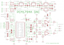
This project was started since last December and this couple of weeks I got some free time to focus on it. The schematic is nothing special just followed TI proposed designed confronting with Andrea Ciuffoli and Pavouk circuits.
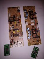
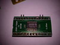
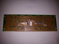
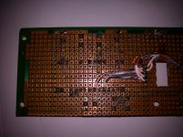
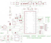
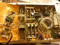
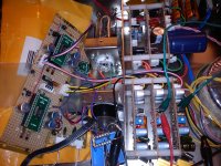
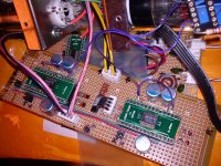
I took some photos showing the main DIR PCB and DAC PCB.
Just like I wrote in the title, unfortunately I burnt 4 of PCM1794 up till now. I can't believe that these chips are so fragile...
I checked the layout many times but can't spot the problem.
Power supplies are shunt regulators which worked flawless and considering the current limiter that prevent short-circuit at the output.
The situation is this, once the power is on the 3.3VDD of DAC starts to decrease and the DAC increases in temperature which seems like a shortage somewhere. First with the 3.3VDD power rail, and a few seconds later the 5V VCC starts decreasing too.
This problem is so weird... Is there anyone having the same problem with this DAC? Any suggestion will be welcome!! Thanks.
Well, the reason is very simple, just want to make an A/B test with the current DAC I'm listening to, TDA1541 NOS, and to share some fun with friends.
This project was started since last December and this couple of weeks I got some free time to focus on it. The schematic is nothing special just followed TI proposed designed confronting with Andrea Ciuffoli and Pavouk circuits.
I took some photos showing the main DIR PCB and DAC PCB.
Just like I wrote in the title, unfortunately I burnt 4 of PCM1794 up till now. I can't believe that these chips are so fragile...
I checked the layout many times but can't spot the problem.
Power supplies are shunt regulators which worked flawless and considering the current limiter that prevent short-circuit at the output.
The situation is this, once the power is on the 3.3VDD of DAC starts to decrease and the DAC increases in temperature which seems like a shortage somewhere. First with the 3.3VDD power rail, and a few seconds later the 5V VCC starts decreasing too.
This problem is so weird... Is there anyone having the same problem with this DAC? Any suggestion will be welcome!! Thanks.
Attachments
Recently I'm DIYing a PCM1794 based DAC, for me and for some friends of mine.
Well, the reason is very simple, just want to make an A/B test with the current DAC I'm listening to, TDA1541 NOS, and to share some fun with friends.
This project was started since last December and this couple of weeks I got some free time to focus on it. The schematic is nothing special just followed TI proposed designed confronting with Andrea Ciuffoli and Pavouk circuits.
I took some photos showing the main DIR PCB and DAC PCB.
Just like I wrote in the title, unfortunately I burnt 4 of PCM1794 up till now. I can't believe that these chips are so fragile...
I checked the layout many times but can't spot the problem.
Power supplies are shunt regulators which worked flawless and considering the current limiter that prevent short-circuit at the output.
The situation is this, once the power is on the 3.3VDD of DAC starts to decrease and the DAC increases in temperature which seems like a shortage somewhere. First with the 3.3VDD power rail, and a few seconds later the 5V VCC starts decreasing too.
This problem is so weird... Is there anyone having the same problem with this DAC? Any suggestion will be welcome!! Thanks.
These sorts of problems are very difficult to diagnose from afar. It definitely sounds like you have blown those DAC chips if they get hot while the power supply voltage also sags. So long as you are not subjecting the DAC outputs to significant voltage, it should not be possible to damage the chip through it's outputs. They are inherently current limited by design.
My suggestion is to re-check a few basic things. First, check for any shorts between adjacent DIP socket pins, with the DAC removed, of course. Also, check for unexpected shorts from each socket pin to ground. Should you find no errors, then make sure that your point-to-point hand wiring is absolutely correct (confirm all hand wired paths between the terminating nodes of that path with a continuity checker), including that you have not misidentified pin-1. I can say from my own experience that we often see what we expect to see, rather than what is actually there.
Beyond those things, I can only suspect that you may be damaging the DAC chips simply through handling them should you not be observing proper anti-static procedures. Let us know what you find.

Last edited:
I'd almost suspect that the supply and grounds somewhere are swapped or you are delivering way more than 3.3V on the digital side or 5V on the analog side. This is a unipolar dac so make sure that the supply polarities are correct on all supply pins.
I've used the PCM1794A and PCM1798 successfully in a number of designs but do not use shunt regulators in any of them. Make absolutely certain that if the shunt regulators overshoot at power up that they do not exceed the absolute maximum supply voltage ratings of the PCM1794A - this is another thing I would suspect. (Strongly!)
Make sure that the supplies come up together, I'm not sure that the PCM1794A is/is not sensitive to power supply sequencing. (Mine come up in lock step well within a couple of ms.)
Handle according to good ESD procedure as these are static sensitive and will self destruct if exposed to excessive static discharges.
http://www.ti.com/general/docs/lit/getliterature.tsp?genericPartNumber=pcm1794a&fileType=pdf
FWIW I do not like those like those not so little dac boards as there should be decoupling of the reference and supply pins within mm of the device package for best performance. I'm wondering what sort of decoupling you have..
What are you doing for I/V conversion?
Can you post a schematic of what you are attempting to do? And unfortunately I have a lot of concern about your build technique which is not appropriate for high speed, high performance digital/mixed signal devices. I don't see any evidence of good low impedance digital grounds, power or decoupling and rather a lot of very small wire tack soldered here and there. I also see what appears to be a highly capacitive implementation of I2S..
FWIW Both the 1798 and more particularly the 1794A are excellent performers with careful implementation. Worth the effort to sort out.
At the first look, Vcc and Vdd looks ok. Sice you have the Iout pins bended out and missing on the board, I assume that you are inserting it right.
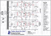
My first suspect would be the power supply. I never trust a shunt-type power supply. Not without crowbar protection, but sometimes even that is slow to react to voltage spikes (depends of the capacitor on output of regulator).
My first suspect would be the power supply. I never trust a shunt-type power supply. Not without crowbar protection, but sometimes even that is slow to react to voltage spikes (depends of the capacitor on output of regulator).
An externally hosted image should be here but it was not working when we last tested it.
I've used the PCM1792/94 for a long time now and find them to be quite resilient but they do not take well to certain things.
They will survive slightly higher power rails for a sort period of time. I once shorted the 3.3 and 5 volt rails together by mistake and one 1792 got very hot, smoked in fact, I quickly turned everything off, then solved the problem and the chip still worked perfectly and measured just the same.
One thing the chips do not like is having the ground pins unconnected by mistake, as in perhaps the pins aren't soldered down correctly. This will cause them to heat up and they will fail as a result. If you manage to turn them off before they totally cook themselves then they do survive, so they are quite robust as things go.
The PCM1792/4s will operate fine without anything connected to their outputs. If your I/V stage is causing problems then disconnecting it could be a way of finding this out. I had a discussion with an engineer at TI who basically said that the chip could possibly become unstable under capacitive loading, so if your I/V stage is somewhat different then this could be causing the issue.
As Ken mentioned the outputs are somewhat current limited, but this is more a case of the output current is usually controlled directly by the DAC chip as a result of how it functions. However under inappropriate circumstances it would probably be possible to force them into outputting too much current.
As you've mentioned that the supply rails are sagging this implies that something is forcing the chip into oscillation or that something is being forced to work harder then it should.
The outputs of the DAC chip are biased around the 10k resistor that connects to pin 20. The lower the resistors value the higher the output current. If you were to connect this pin to ground by mistake or have it shorted to something else then this would easily force the outputs into pushing more current then they are capable of. The 1792/4 always has a standing current flowing into the outputs, so even without any music playing the DAC is pumping current. If you disconnect the I/V stage then this current ceases to flow, if you measure the drawn current on the 5volt supply line it changes with the sampling frequency and rate of over sampling chosen, but typically it should not exceed around 50mA, if you disconnect the I/V stage this will fall down to only a mA or so. This might be helpful in figuring out where the problem is.
Ken,
I revised the layout once again and did try point-to-point check: SSOP adaptor pin to IC pin -> socket pin to IC pin. There was no open circuit.
The same 3.3VDD provide both DIR9001 and PCM1794, however DIR9001 was still alive.
May be I didn't care too much about the ESD, but DIR9001 was soldered the same way PCM1794 was, so I'm quite confusing about this...
Kevinkr,
there is no way that I could swap the powers, since the output connector for 3.3V and 5V are totally different: 4-pin connector and 2-pin connector. I purposely choose two different connectors to avoid this problem happen.
The supply voltage was adjusted up to the value before connecting to the board.
Sorry for my unprofessional building technique, the resources are quite limited however the signals (LRCK, DATA, BCK, SCK) from DIR9001 were quite pleasant and my oscilloscope showed decent output wave.
SoNic_real_one,
I'm not that hostile against the shunt regulator, after all it provides a very stable voltage that satisfied my need. Please check out the attachment.
The Iout pins were bent so I could easily connect to tube grid.
5th element,
today I took another try with others PCM1794s handling with care, soldered them with solder iron, and again, 3 more were dead...
Just being curious, how did you solder them? I tried different soldering method (except reflow), would you mind share your method?
After the chip were burnt (burnt but without smoke), I measure the resistance between the 3.3VDD pin - DGND and 5VCC - AGND; I read a ~130ohm which differs from the initial resistance I measure before applying power, above some kohm.
I did try using normal voltage regulator instead of the shunt regulator, 7805 and TPS7A4533. But both of them got hot, too hot.
I think I should remove the socket and soldered the adapter directly on the PCB...
Attachments
Just being curious, how did you solder them? I tried different soldering method (except reflow), would you mind share your method?
Over the years I have used various methods for soldering SMD chips but all have worked. The first is simply soldering the individual legs with a very fine soldering iron and a magnifying lens. The second is using a large soldering iron tip and flooding the legs and pads with solder, then using solder braid/wick, to remove the excess solder. The third and by far the best imo is using solder paste. I solder the chip in place by soldering down 1 or 2 pins, usually two, one at each end of the chip and on opposite sides. I then wipe solder paste into and around the pins/pads, then heat with a heat gun/paint stripper hot air gun. This melts the solder and everything solders nicely into place by surface tension. Sometimes I need to use the solder braid if I've used too much paste, but this technique works the best.
After the chip were burnt (burnt but without smoke), I measure the resistance between the 3.3VDD pin - DGND and 5VCC - AGND; I read a ~130ohm which differs from the initial resistance I measure before applying power, above some kohm.
If the resistance changes then that means you've most likely cooked the chip real good. I have never damaged a PCM1792/4 due to ESD and I don't wear a static distarge bracelet either. I do make sure to connect myself to earth by touching something appropriate to discharge myself before handling chips though.
I did try using normal voltage regulator instead of the shunt regulator, 7805 and TPS7A4533. But both of them got hot, too hot.
Linear regs tend to get quite hot, even with low current, if the voltage they are stepping down is quite large. They obviously get a lot hotter if the current drawn is high, which it sounds like is happening here.
I think I should remove the socket and soldered the adapter directly on the PCB...
This is unlikely to solve your problem. Looking at the schematic for you I/V converters I can't help but notice that your circuit is quite different from what TI recommend you do on the outputs.
First of all the outputs of the DAC chip are designed to work into a virtual ground, ie zero ohm source resistance. From your circuit diagram is looks like your I/V stage isn't doing this. The second thing that jumps out at me is the 2n2 cap that you've got soldered across the outputs of the DAC. This is the one thing the TI engineer advised against me doing as the chip would be unlikely to enjoy the capacitive load.
As before I recommended disconnecting the DAC chip from the I/V stage and see what happens. From my experience chip wont burn if the I/V stage is disconnected, but the chip can burn if something goes wrong in the I/V stage.
I believe that's a 10k surface mount resistor that wmincy has between pins 19 and 20.
Yes, I can see that now. My eyesight isn't what it once was. Looks like an SMD resistor, as seen edge on. I thought maybe I was seeing a piece of wire. It's very unfortunate, that he is having such catastrophic failures of multiple DAC chips without ready determination of the cause.
It is unfortunate indeed. I've fried a few PCM1792/4s in my time, mainly through stupid mistakes, but on the whole they tend to be very forgiving of circuit errors and implementation.
On the digital side (pins 1-14) there are very few things that could go wrong. 11 of the pins are 5 volt tolerant and can be set either high or low without damaging the chip. This only leaves three pins, zero, +3.3 and ground this should be fairly easy to trouble shoot.
The analogue side is a little more complicated so it's far more likely that this is where the problems are being caused, nevertheless the analogue side is still quite forgiving if some connections aren't made correctly.
wmincy, as you've tried multiple chips and have also had to have soldered many of them in place it stands to reason that the adaptors and your soldering isn't at fault. In other words I can see you perhaps botching the soldering once, or perhaps twice, but not in the same way multiple times.
One thing I've taken to when powering on any of my PCM1792/4 implementations is to wire a 50mA fuse in line with both the 3.3 and 5 volt rails. Doing this has saved me from a couple of burn outs in the past. I use slow blow type fuses and the handy thing is that when something is wrong they glow hot and the fuse wire resistance increases. This acts to lower the current draw and protect the chip without blowing the fuse! I guess this wouldn't happen if the voltage were perhaps a lot higher, but as is the fuses act just like a bulb tester in a power amp.
wmincy,
It is unfortunate that so many chips have been destroyed. It is said that one definition of insanity is trying the same thing over and over, expecting different results. Are you ready to try something else?
The data sheet for the PCM1794 as well as the data sheet for the eval board give a proven design. I duplicated these for my first attempt at a PCM1794 DAC board. This first attempt worked. Then I used this board as a base for experimentation - some things worked and others didn't, but this was the cost of an education.
Why not try this approach and see how it works for you?
Dave
thanks guys for your feedback.
Today I gave another try: I checked the layout again, point to point test. And I also change the socket. Then with a new PCM1794 soldered, I crossed my fingers and... I heard sound coming from the earphone!! Hurrah!!
I left it played for a while but I was too early to cheer. I switched off and switched on to make sure things are going right, but bad things happened... once again, the chip was fried. Then I checked for pin shortage and the resistance value between VCC1 and AGND was low enough to behave like a short circuit... so frustrated I'm...
But I'm now sure that the layout was ok, otherwise the would be no sound at all.
I think tomorrow I'm going to switch to voltage regulator, I just want to make sure whether the shunt regulators were defected or not.
This DAC is making me crazy!!!!
But I'm now sure that the layout was ok, otherwise the would be no sound at all.
I think tomorrow I'm going to switch to voltage regulator, I just want to make sure whether the shunt regulators were defected or not.
This DAC is making me crazy!!!!
no, you know that your layout is ok for a few minutes use before catastrophic chip death
, big difference. the shunts could very well be the culprit, but I would be looking to start again with another layout if I were you, just to make sure there is no gremlins you cant seethanks guys for your feedback.
Today I gave another try: I checked the layout again, point to point test. And I also change the socket. Then with a new PCM1794 soldered, I crossed my fingers and... I heard sound coming from the earphone!! Hurrah!!
I left it played for a while but I was too early to cheer. I switched off and switched on to make sure things are going right, but bad things happened... once again, the chip was fried. Then I checked for pin shortage and the resistance value between VCC1 and AGND was low enough to behave like a short circuit... so frustrated I'm...
But I'm now sure that the layout was ok, otherwise the would be no sound at all.
I think tomorrow I'm going to switch to voltage regulator, I just want to make sure whether the shunt regulators were defected or not.
This DAC is making me crazy!!!!
Yesterday 4/18 I did try switching to voltage regulator, and removed 2x low ESR capacitors from the +5VCC power rail (which turns out that the problem had nothing to do with the capacitors), however I still stick to the same PCB, same layout... sorry qusp, i'm quite insist about the correctness of the layout (I made it with the use of EWB). Besides these minor changes, I soldered the chip with less, almost zero, soldering flux and after soldering I cleaned the adopter with alcohol. And this time, guess what, it worked, and it worked so well that I left it running for nearly 1 hour!!!
Yes, finally it worked!! I might guess that before I put too much flux without cleaning it, may be some of the residual tin was causing short circuit. I went to bed and left this hypothesis to be verified the next day.
And today, after back from work, I tried to do the same thing with another chip, the last one: with little, very little amount of soldering flux and alcohol for cleaning. Another attempt I did was to switch back to shunt regulator. And now with 2x PCM1794 I run them into mono mode (1 chip for 1 channel). Voila, perfectly functioning!! I suffered too much lately, especially with 10x chips detroyed.... now I really can enjoy having a good sleep!!
Next step, I will connect the output to the tubes, CV6. And will see how nice will be the sound of this DAC.
Attachments
Last edited:
I might guess that before I put too much flux without cleaning it, may be some of the residual tin was causing short circuit. I went to bed and left this hypothesis to be verified the next day.
9 times? that seems very unlikely
9 times? that seems very unlikely
I agree, something here doesn't quite add up. I have had PCBs literally covered with flux and with lots of old burned flux caked around the PCB pads. I have never had any kind of problem like this.
One thing I can mention however is that the stability of the chips can be on a knife edge if you're messing about, ie leaving ground pins unconnected as a way of trouble shooting
. What this means is that on turn on, they will function fine and be stable. If turned off then on again they can be unstable and will oscillate and explode. If you're watching what you are doing, you can turn it off before they break, but you need a finger on top of the chip to let you know that it's getting too hot and needs to be turned off. If you keep turning them on and off you will get a turn on where they are stable and they will remain stable. Sample rate changes can cause them to become unstable too.The fact that one worked, then smoked the next day makes me think that something is amiss. Usually nothing will happen to electronics when simply left over night, this isn't to say that you haven't solved the problem, but I would still be on your guard.
As to the power regulators, I wouldn't expect these to be the cause. Except for the 5volt line, you have been powering other chips from the 3.3v line and they have survived.
Do bare in mind that some regulators do not like having large amounts of capacitance or ultra low ESR capacitors placed on their outputs as it can cause instability. The PCM1794s will function just fine with the 10u per pin as described in the datasheet. There is no reason to use a larger value capacitor here. If you really want to get a lower ESR part near the chip pins then go for a higher voltage version of the same value and series.
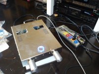
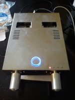
after weeks of work since i burnt the last PCM1794, I found out that the chips were burnt was due to bad grounding and the problem was solved with a star grounding method.
Now the DAC works happily.
I noticed that the output level after tube stage was quite high so I reduced the I/V resistor so the level is contained.
At the first listening impression, I should say the details are amazing. The tube output, single triode CV6 "rabbit head" in anode follower biased at 10mA, gives a full body, transparent sound which is very very pleasant.
However, comparing to TDA1541, the sound was slightly brighter and a little bit invasive.
Overall, I'm quite satisfy with this new toy.
Here are some photos:
Attachments
yes qusp,
After the first DAC i managed to build other 3 units of the same configuration.
I noticed that if i didn't clean the PCB and the SSOP adaptor properly, once power on, i would see some sparks between the pins, mostly occured on the adaptor.
So after these instructive experiences, i finally learn to clean every time i finished soldering. And I didn't burn a PCM1794 anymore (finger crossed)
Many sites also remarked that the cleaning of the residual flux and stray micro solder balls (squirt over the pcb during soldering, not so visible to the naked eyes) is necessary.
Well, i learned a lesson... in the hard way...
- Status
- This old topic is closed. If you want to reopen this topic, contact a moderator using the "Report Post" button.
- Home
- Source & Line
- Digital Line Level
- PCM1794A tube-output DAC.... 4 chips detroyed