I recently completed a DAC with NOS AD1865 and a salas shunt regulators I now need to decide on a IV stage for it I want it to be solid state and discrete. I have found two circuit that look the best to me the "Pass D1 IV" and the "Pedja Rogic´s Discrete Diamond Non-Feedback I/V Stage" I would like to know which one of these circuits have the best performance "subjectively" (sound quality) - test figures THD, ect. ")
Silicon chip an Australian magazine recently published a dac that ised a discrete I to v stage. It was a reasonably conventional discrete op amp, which in my mind was the right choice. The measured performance was very good indeed.
Most of the silicon chip stuff is published in Europe under a magazine (guessing here) named something like epn
I am sure there would be an Aussie or kiwi who has a copy of the article. FYI they used a cl4398 dac but that should not affect the approach to I to v
Most of the silicon chip stuff is published in Europe under a magazine (guessing here) named something like epn
I am sure there would be an Aussie or kiwi who has a copy of the article. FYI they used a cl4398 dac but that should not affect the approach to I to v
Last edited:
I recently completed a DAC with NOS AD1865 and a salas shunt regulators I now need to decide on a IV stage for it I want it to be solid state and discrete. I have found two circuit that look the best to me the "Pass D1 IV" and the "Pedja Rogic´s Discrete Diamond Non-Feedback I/V Stage" I would like to know which one of these circuits have the best performance "subjectively" (sound quality) - test figures THD, ect.
To determine which one has the best subjective sound quality will require that you audition both with your own ears. Simply wire both I/V circuits on individual breadboards and compare.
Thanks I will compare the two stages when I get the parts to build them.
Also, I built the Pass D1 IV and there in a slight amount of hum. the layout is good (ground plane). the the wires are all hooked up good. could the hum be caused by no signal at the I-Input (I have no DAC chip yet.)?
Also, I built the Pass D1 IV and there in a slight amount of hum. the layout is good (ground plane). the the wires are all hooked up good. could the hum be caused by no signal at the I-Input (I have no DAC chip yet.)?
I have some experience with the AD1865, as I've designed and built two different DACs using it. The AD1865 is relatively rare, in that it is a current output DAC with a high output voltage compliance. This enables the use of a passive resistor I/V, which is the best performing type of I/V, assuming the DAC has a high voltage compliance, which most don't. I've used I/V resistor values as high as 330 ohms on AD1865 without problem. I find that passive I/V with this DAC chip subjectively supremely clean sounding.
What passive I/V with the AD1865 further enables is the A.C. coupling of the DAC output to your linestage without any intervening circuitry. Most solid-state linestages have enough gain for this, most of which is thrown away anyhow, with typical 2VRMS DAC output voltage levels. The output impedance will be the 1.7K ohm AD1865 output impedance in parallel with whatever value of I/V resistor you've slected. In other words, it will be low enough to drive your quite effectively.
What passive I/V with the AD1865 further enables is the A.C. coupling of the DAC output to your linestage without any intervening circuitry. Most solid-state linestages have enough gain for this, most of which is thrown away anyhow, with typical 2VRMS DAC output voltage levels. The output impedance will be the 1.7K ohm AD1865 output impedance in parallel with whatever value of I/V resistor you've slected. In other words, it will be low enough to drive your quite effectively.
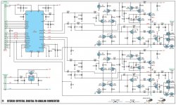
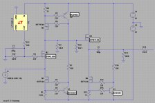
I wish I could use passive conversion but I use the Pass B1 preamp which has no gain and an amp the requires 2v P-P. I'm thinking of making PCB's of this IV stage which is a modified Pass D1 can somebody tell me if my rendition of the circuit will work as good as the original (it simulates well).
Attachments
You should definitely check out the CEN - SEN here:
http://www.linearaudio.net/userfiles/file/Didden LA Vol 2 EUVL.pdf
jan
http://www.linearaudio.net/userfiles/file/Didden LA Vol 2 EUVL.pdf
jan
the D1 can sound very good indeed, I have no noise whatsoever even when no music is playing. I havent tried anything like your circuit with the servo, I use a modified balanced version without the buffer with my sabre dac.
dubbed the NTD1
i'm trying the sen as well, but yes, particularly for the balanced ES901X v0.18 version its not really tricky, just extensive due to the sheer number of supplies or batteries needed so its taken me a while to get it done, even with batteries the power supply + bias ref is a few times bigger than the circuit. sounds like its worth some effort though from reports so far
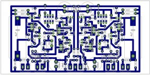
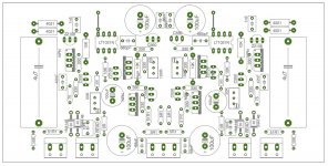
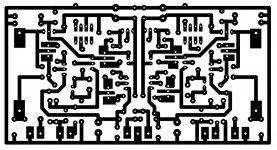
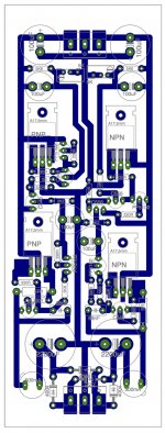
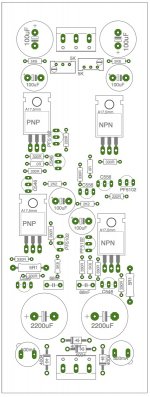
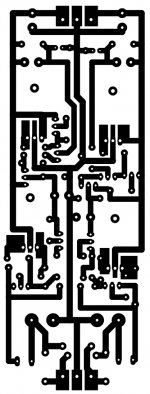
I created a layout for the circuit. I think i'm going to etch some pcb's.
It is using the salas shunt for the power supply.
It is using the salas shunt for the power supply.
Attachments
I wish I could use passive conversion but I use the Pass B1 preamp which has no gain and an amp the requires 2v P-P. I'm thinking of making PCB's of this IV stage which is a modified Pass D1 can somebody tell me if my rendition of the circuit will work as good as the original (it simulates well).
You're correct, the Pass B1 would preclude the mode I had suggested. You would need about 20dB of gain from the linestage.
That circuit seems to be hard to implement (floating supply, battery power) so I think I'm going to stick with the D1
That's interesting - there was just a discussion there that a battery was sooo much simpler than a good, high performance mains supply...
jan
That's interesting - there was just a discussion there that a battery was sooo much simpler than a good, high performance mains supply...
jan
no, the discussion ended that its simpler than a high performance floating power supply good enough to drive the circuit that has not so great psrr =D its not so much difficult to use the batteries, just a bit of a pita. if you use the NIMH in the bom its not so difficult as lifepo4, but you still must either remember to charge, or come up with a simple switch to do it automatically. again not so much hard, just something additional that you dont normally need, you need a simple control/indication circuit and an additional power supply as well as your power supply
- Status
- This old topic is closed. If you want to reopen this topic, contact a moderator using the "Report Post" button.
- Home
- Source & Line
- Digital Line Level
- Need help choosing a discrete IV stage