I recommend making it so there is patterns for to247 mosfets as well as to220, as opc found there are some really nice high gM devices out there in the larger package and this lowers inputZ and thus lowers THD, running them at higher voltages than the Pass version helped in this regard as well. not sure whether salas shunts are the best choice, great regs but this IV already puts out a fair bit of heat
Hi benproiii, I just built the Pedja I/V using the AD844 (The AYA DAC II version). I'm using it with the TDA1541A. So far I am extremely happy with it. I understand the discrete version could well be better. Not difficult to build just be careful of the jfet pinouts. Toasted my first 2 AD844's by a dumb mistake. I was able to adjust to better then a 0.1 millivolt offset on the second attempt. Not much drift. Dave ")
I have some experience with the AD1865, as I've designed and built two different DACs using it. The AD1865 is relatively rare, in that it is a current output DAC with a high output voltage compliance. This enables the use of a passive resistor I/V, which is the best performing type of I/V, assuming the DAC has a high voltage compliance, which most don't. I've used I/V resistor values as high as 330 ohms on AD1865 without problem. I find that passive I/V with this DAC chip subjectively supremely clean sounding.
What passive I/V with the AD1865 further enables is the A.C. coupling of the DAC output to your linestage without any intervening circuitry. Most solid-state linestages have enough gain for this, most of which is thrown away anyhow, with typical 2VRMS DAC output voltage levels. The output impedance will be the 1.7K ohm AD1865 output impedance in parallel with whatever value of I/V resistor you've slected. In other words, it will be low enough to drive your quite effectively.
Ken do you know if the AD1862 shares a similiar highesh voltage compliance tolerance? It looks like a good candidate for the Cen but I have never tried my AD1862's with an IV that has an input impedance greater than 1.
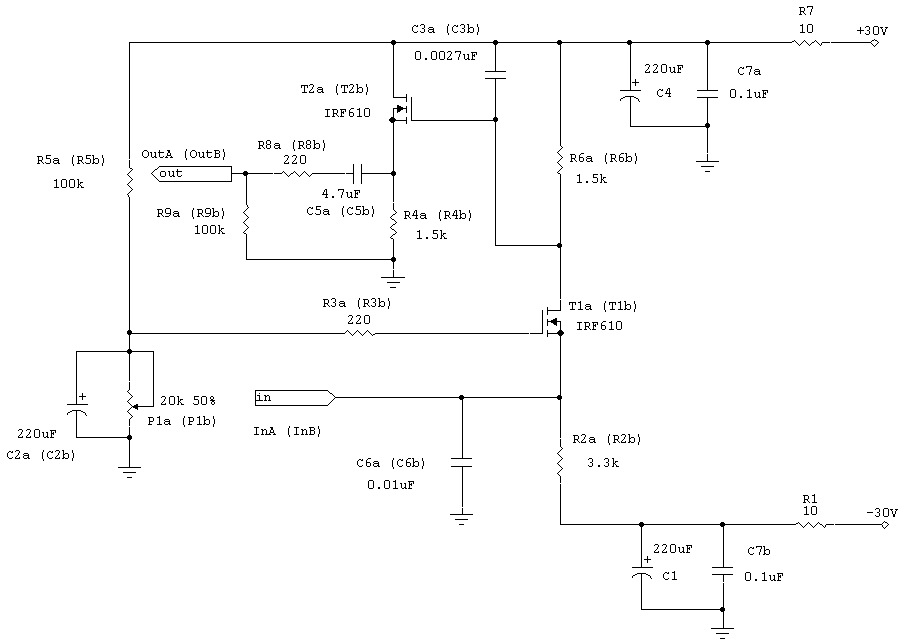
I have found that the ZVN2106 Vertical FET does not drift it's DC offset as much as the IRF*** I can get it <1mv and it stays there, the precision reference in the circuit helps too. I will test there SQ of the circuit as soon as my CS8414 comes in the mail.
I guess you have to decide whats more important, a few mv of drift or higher performance in the actual performance of the IV stage? I realize the servo is a thought experiment for you, thus important, but the performance of this IV is directly and rather profoundly related to the transconductance of the chosen mosfet, also the transconductance we found gets higher as the supply voltage (and thus dissipation) gets higher
Ken do you know if the AD1862 shares a similiar highesh voltage compliance tolerance? It looks like a good candidate for the Cen but I have never tried my AD1862's with an IV that has an input impedance greater than 1.
Hi regal,
Sorry, I don't have any experience with the AD1862. I might, however, suggest conducting the following test on a single channel, thereby exposing only a single AD1862 to this experiment:
1) Disconnect your present I/V circuit and instead connect a 100 ohm I/V resistor from the AD1862 output to ground.
2) A.C. couple the output directly to your linestage, which hopefully has around 20dB of gain, with as good a quality capacitor as you have ready access to.
3) Make sure the volume control is set at the fully attenuated position before powering your system. SLOWLY bring the volume up to your usual levels, carefully listening for any signs of distortion along the way. A 100 ohm passive I/V value would produce a peak signal voltage of 100mV on the AD1862 output, which shouldn't cause any damage to your AD1862.
4) If the sound is clean, replace the 100 ohm resistor with a 150 ohm resistor and repeat step 3. Then, once more, using 200 ohms or so. I use 191 ohm passive I/V resistors on my AD1865 DAC.
Should only the 100 ohm I/V resistor sound clean, that would likely still be high enough for direct (A.C. coupled) connection to a 20dB or 26dB gain linestage. If using even the 100 ohm resistor reveals signs of distress, then the AD1862 probably isn't a good candidate for passive I/V.
Last edited:
i'm using batteries right now and use them extensively, much more than in single stage, its not that, its 8 of them and charger, plus bias supply in a case that is already full to the brim. hasnt stopped me playing on the bench (just one channel so far), but you cannot pretend its not an obstacle.
one copper/teflon cap in my signal path doesnt bother me a great deal no and given all the rest of the way to the speakers is totally DC coupled including the speakers themselves, probably not such a bad safety measure
one copper/teflon cap in my signal path doesnt bother me a great deal no and given all the rest of the way to the speakers is totally DC coupled including the speakers themselves, probably not such a bad safety measure
Last edited:
- Status
- This old topic is closed. If you want to reopen this topic, contact a moderator using the "Report Post" button.
- Home
- Source & Line
- Digital Line Level
- Need help choosing a discrete IV stage