The CMRR only tells us how well the trafo rejects any common-mode signal relative to the differential mode signal. It does not give us an indication of how easily common mode noise enters the DAC as a whole system. For the CM noise the interwinding capacitance is a key factor, not the CMRR.
The loop is opened at DC but is still there at RF frequencies via the parasitic capacitances.
I stand corrected. I have lying around the SC937-02, shielded 1:1 version. According to the manufacturer it has 1 pF capacitance.
Would that be any good or are there better still?
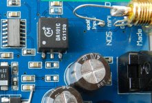
That's a helpful pic, thanks. I note a couple of things - the tracks to the Murata trafo run close to the ground plane - there will be some stray capacitance there to the plane. I don't see where the secondary of the trafo goes to - is it going to a differential input receiver? Or is one side of the trafo secondary going to the plane? If so, then that's one point to lift from the plane and wire back to the input 0V.
Here's a pic from a different angle. One side indeed goes to a plane. But this is a six layer pcb, so it might very well be that it's star grounded after all. Lots of layers to put planes in.
Murata doesn't tell us what the interwinding capacitance is in the datasheet. Lower is better when considering CM noise.
Well, here it says 52.1 without unit but I'm guessing it's pF. With respect to the SC937-02 that would seem excessive...
Attachments
Hi Guys:
The trouble is that a transformer (or a differential amplifier, for that matter) is not very effective at rejecting common-mode noise entering on an unbalanced cable interface. Common-mode rejection comes from having the ratio of the impedances on each conductor match. In an unbalanced 2-conductor cable, while it is easy to control the impedance ratio on the signal conductor, it is not easy to control the ratio on the ground conductor. Such control is inherently enabled via a balanced 3-conductor cable.
The solution is to convert the unbalanced RCA based S/PDIF coaxial interface in to a balanced one, as far as the impedance terms are concerned. This does not require differential signal drive nor XLR connectors, so can be achieved with both RCA and BNC terminated cables, and completely at the DAC side of the interface too.
Last edited:
I stand corrected. I have lying around the SC937-02, shielded 1:1 version. According to the manufacturer it has 1 pF capacitance.
Would that be any good or are there better still?
That's about as good as they get. I think SC has a 0.5pF but the difference is going to be minimal. There's already more than that in stray to the top plane.
Here's a pic from a different angle. One side indeed goes to a plane. But this is a six layer pcb, so it might very well be that it's star grounded after all. Lots of layers to put planes in.
Yes but the point is - its noisy. Keep it to its own dedicated ground wire or the noise spreads around. Its via'd into the top ground plane - a big no-no for noise. Lift the right-most pin on the trafo and install a dedicated ground wire to it.
Well, here it says 52.1 without unit but I'm guessing it's pF. With respect to the SC937-02 that would seem excessive...
It says dB just above

So, there seem to be some improvements to be made after all.
Coincidence that the CMRR is 52.1 dB and the interwinding capacitince 52.1 pF, or would this latter value be incorrect?
It says dB just above
Coincidence that the CMRR is 52.1 dB and the interwinding capacitince 52.1 pF, or would this latter value be incorrect?
Last edited:
The trouble is that a transformer (or a differential amplifier, for that matter) is not very effective at rejecting common-mode noise entering on an unbalanced cable interface.
True but here the issue isn't getting enough CMRR as its an unbalanced feed as you note. We're not concerned to reject CM noise on the signal line(s) but rather prevent CM noise getting into the DAC 0V. Its the CM noise which gets to contaminate the ground which degrades the sound - via common ground impedance coupling.
Hi,
This is only true for badly designed/constructed parts (of which there are legions, arguably - as Sturgon's Law applies).
Actually, the true solution is to decouple the DAC's master clock from short term variations of the source clock, no matter if the source is common mode noise or any other one. In principle BTW this is quite trivial, even though in practice it is quite challenging.
Ciao T
The trouble is that a transformer (or a differential amplifier, for that matter) is not very effective at rejecting common-mode noise entering on an unbalanced cable interface.
This is only true for badly designed/constructed parts (of which there are legions, arguably - as Sturgon's Law applies).
The solution is to convert the unbalanced RCA based S/PDIF coaxial interface in to a balanced one, as far as the impedance terms are concerned. This does not require differential signal drive nor XLR connectors, so can be achieved with both RCA and BNC terminated cables, and completely at the DAC side of the interface too.
Actually, the true solution is to decouple the DAC's master clock from short term variations of the source clock, no matter if the source is common mode noise or any other one. In principle BTW this is quite trivial, even though in practice it is quite challenging.
Ciao T

Coincidence that the CMRR is 52.1 dB and the interwinding capacitince 52.1 pF, or would this latter value be incorrect?
I very much doubt they would quote the interwinding cap to a 0.1pF resolution. So I think its not correct as pF.
Last edited:
Now the PCB desingn is bad?
Very definitely. Use of a single all-encompassing ground fill is not a really high-end solution. Check out the Berkeley Alpha DAC for superior grounding practice.
True but here the issue isn't getting enough CMRR as its an unbalanced feed as you note. We're not concerned to reject CM noise on the signal line(s) but rather prevent CM noise getting into the DAC 0V. Its the CM noise which gets to contaminate the ground which degrades the sound - via common ground impedance coupling.
Yes, but even with that objective, having 150 ohms of resistance between component grounds would greatly limit ground loop current flow between those components, compared with having only the resistance of the unbalanced cable's 0-Volt conductor.
Actually, the true solution is to decouple the DAC's master clock from short term variations of the source clock, no matter if the source is common mode noise or any other one. In principle BTW this is quite trivial, even though in practice it is quite challenging.
Ciao T
Yes, managing an NCO, for example, to match the exact long term average frequency of the source oscillator, but at the DAC, is probably the best, but also sophisticated, solution. Such an implementation is, unfortunately, probably not an option for the more advanced diy audiophile.
Last edited:
Yes, but even with that objective, having 150 ohms of resistance between component grounds would greatly limit ground loop current flow between those components, compared with having only the resistance of the unbalanced cable's 0-Volt conductor.
The biggest ground current flow I've measured is in the region of a few 100 uA (this at 50Hz), so I can't see how 150R would make much of a dent in that. Unless it was originating from a lowish source impedance. Mains wiring is the means of coupling CM noise between components, via interwinding capacitance of trafos.
I realise the digital sources I use are down at the lowest end of the market, and their el-cheapo SMPSUs impose some not insignificant CM currents, but these arrive having passed few a few hundred pF of (transformer) coupling capacitance at most. So source impedance tends to be quite a bit higher than 150R at the frequencies they operate at (a few 10's of kHz).
Well... that's weird because on the other hand you defend the technical know-how of the said designer/engineer. How that can be - is he good enginner or a bad one?Very definitely. Use of a single all-encompassing ground fill is not a really high-end solution. Check out the Berkeley Alpha DAC for superior grounding practice.
Is the same story again. Like when the Philips designers show you the appropiate use of their DAC's - with OS. You hail them for designing a good DAC, but you assume that they are completelly idiots about OS.
Actually they have a parallel capacitance and resitor (for electrostatic safety) that have some 4.7...10 nF and 2...4.7 Gohm. Your argument is still valid thou.but these arrive having passed few a few hundred pF of (transformer) coupling capacitance at most. So source impedance tends to be quite a bit higher than 150R at the frequencies they operate at (a few 10's of kHz).
Last edited:
Well... that's weird because on the other hand you defend the technical know-how of the said designer/engineer. How that can be - is he good enginner or a bad one?
I've praised his audacity in designing with a chip which isn't a mainstream audio part - that's not really defending his technical know-how is it? More recognising his creative flair and marketing aptitude. The world of engineers isn't a black and white one though, so engineers have degrees of competence.
Is the same story again. Like when the Philips designers show you the appropiate use of their DAC's - with OS. You hail them for designing a good DAC, but you assume that they are completelly idiots about OS.
No I just claim they either didn't listen to Bitstream carefully enough or they did and have cloth ears
There's nothing intrinsically wrong with OS in my estimation - its a matter of implementation. Noise-shaping is another matter entirely though. Perhaps you're dwelling too much in the world of your own polar (black vs white) thinking - get out a bit more and see how the world is a spectrum of colours?In my polar world I saw engineers bad of good. Doctors bad and good.
Because if a person cares about what is doing, it will teach itself in all the aspects of that job.
Missing some basic knowledge tells me that his skills are low-grade. Mainly due to not caring to be informed and I... won't trust it with nothing else that is higher level on knowledge scale.
But that's me and my experience in this world.
PS: Philips engineers decided that bitstram is good enough to spend hundreds of millions $ in developing and manufacturing. You think they are so dumb (compared with your ability) that didn't listen to their products or the are deaf (compared again to your ability). Hmm... isn't that a little too much ego showing?
I think that there are bad things about S-D but there are also bad things about MB. They know that too, that's why the present day DAC's are a combination of both. They tried 10 bit, 7 bit, now looks like they settled to some 4 bit.
Last edited:
Well in my estimation he got a working DAC out the door and its receiving rave reviews across the board. That's not 'low-grade' - his PCB layout skills could definitely be improved but then again he's not selling this DAC in the high-end marketplace. So perhaps he wanted to keep something in reserve for his upcoming v2.0 at a high-end price-point?
The biggest ground current flow I've measured is in the region of a few 100 uA (this at 50Hz), so I can't see how 150R would make much of a dent in that. Unless it was originating from a lowish source impedance. Mains wiring is the means of coupling CM noise between components, via interwinding capacitance of trafos.
I realise the digital sources I use are down at the lowest end of the market, and their el-cheapo SMPSUs impose some not insignificant CM currents, but these arrive having passed few a few hundred pF of (transformer) coupling capacitance at most. So source impedance tends to be quite a bit higher than 150R at the frequencies they operate at (a few 10's of kHz).
I'm not sure that I exactly follow which CM currents you believe need to be suppressed on the 0V line? Are you only refering to SMPS induced high-frequency reactance? Most practical size CM filters do nothing at lower frequencies, such as 50Hz. Balancing an unbalanced input seems the most practical and least inexpensive means of improving CMRR via a transformer coupled input, especially at low freqiencies. Perhaps, I'm failing to understand your concern?
Last edited:
Or... you are wrong about the groundingThat's not 'low-grade' - his PCB layout skills could definitely be improved but then again he's not selling this DAC in the high-end marketplace. So perhaps he wanted to keep something in reserve for his upcoming v2.0 at a high-end price-point?
I'm not sure that I exactly follow which CM currents you believe need to be suppressed on the 0V line? Are you only refering to SMPS induced reactance?
Any currents which impose voltage drops between notionally identical 0V reference points in the circuit. SMPSUs are the main source, but the digital logic inside a transport can add much higher frequencies to the SMPSU payload, albeit at a lower amplitude. Then there's the possibility that external devices on the mains (like LCD TVs with their large CCFL SMPSUs) might impose more crud. We'd ideally not want any of this stuff to make its way between the 0V points of the design via coupling through the SPDIF input.
Well in my estimation he got a working DAC out the door and its receiving rave reviews across the board. That's not 'low-grade' - his PCB layout skills could definitely be improved but then again he's not selling this DAC in the high-end marketplace. So perhaps he wanted to keep something in reserve for his upcoming v2.0 at a high-end price-point?
Not to mention that if he is the one-man shop I've seen reported, he's unlikely be an expert at all facets of product design, development, and production. Too much to expect of one person, I should think.
- Status
- This old topic is closed. If you want to reopen this topic, contact a moderator using the "Report Post" button.
- Home
- Source & Line
- Digital Line Level
- Metrum Octave Dac - What are the Chips used