Hi Everyone.
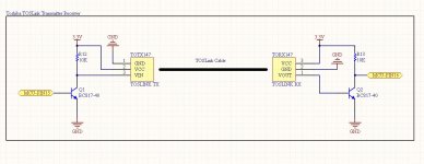
I made a PCB with TOTX147 and TORX147. Here I just want to turn "ON/OFF" TOTX and detect the VOUT signal from TORX when optical cable is connected with TX and RX. I am controlling TOTX and from Microcontroller and detecting the TORX VOUT using LED.
The problem I am facing now .... when TOTX and TORX both are connected (Soldered) on my PCB then with TOTX ON/OFF, TORX not generating any VOUT. But I can see the RED LED on TOTX gets ON/OFF.
But If I remove the TOTX from my PCB (TORX still soldered on PCB) and solder wires (3 wires for VCC, VIN and GND of TOTX) from TOTX to PCB Pads (where TOTX was soldered) then TORX is working fine with TOTX ON/OFF.
I tried many time ... with solder and unsolder TOTX but same result. With TOTX connected with PCB through Wire the system working but of TOTX directly soldered at the same point (where I connected Wires) then system not working. I don't know what is happening behind those wires ...
Note: The system working with when I soldered 3 wires each are around 4 Inch.
If I use short wires like 1 Inch then system not working (behaves like, TOTX soldered on PCB).
FYI, my PCB detail is: Track width 10mil, PCB Clearance is also 10mil.
Is there any special requirements for TOTX147 and TORX147 to PCB design, like ... Track Width/Clearance, Impedance Match etc etc ???
Thanks in advance. Waiting for your advice.
Regards.
Sakibnaz.
Just one wild guess:
Perhaps the TOTX becomes unstable, generating a pulsating optical output signal (probably in the MHz range), when you connect it via long wires?
I assume you have a decoupling capacitor on the PCB even though it is not shown on your schematic. Normally the TOTX (and TORX) should be decoupled properly.
I don't think the TORX likes "DC" signals = constant light. At least not according to the data sheet. But perhaps the (assumed) missing or insufficient decoupling when using long wires, is what makes it work, if the TOTX becomes unstable?
You should also connect a resistor in series with the base of Q2 and perhaps Q1, depending on how the MCU drives the transistor.
Hello.
- I did not use the Capacitor and Inductor which mentioned on TOTX and TORX Datasheet. I connect the TX and RX directly as like my Schematic. Is this can be the issue?
- As I said before my PCB is 10mil Track Width and 10mil Clearance. Is it ok for drive TOTX and TORX?
- At my PCB I used GND Plane .... Somehow is it possible, GND Plane making this problem to drive TOTX when its soldered on PCB?
Thanks for reading.
Sakibnaz.
JensH is right.
It is mandatory that you fit a decoupling cap as close as possible to the TORX and TOTX power supply pins. This can be easily achieved because the power supply pins are near one another so you can solder 100nF in 0805 package on the bottom layer, directly on the pins.
Also , cut the tracks with 3v3 supply that go to the TORX and TOTX and solder a ferrite bead in series. I used 600ohm @ 100KHz
I understand ... next design I'll include the L and C for sure.
But my ques is ... if the problem due to missing L and C (of TX and RX), so why its working when I am connecting TOTX with PCB through Wires?
Another point, I also tested this TX and RX operation on Breadboard without this L and C, then also the system works. But all the problem only happening when I am connecting both TX and RX on PCB.
Any idea please ....
Regards.
Sakibnaz.
As I tried to explain: perhaps it works, because it becomes unstable due to the missing decoupling! As I wrote, the TORX does not like a "DC" signal. The data rate should be minimum 0.1Mb/s and maximum 15Mb/s according to the data sheet.
And it is specifically pointed out: "When non−modulated signal (optical all high or all low level signal) is inputted, output signal is not stable." So, no guaranteed operation with constant ON or constant OFF signals.
I assume that there is some sort of AC coupling internally, to adapt to different light levels and adjust the receiver to the optimum threshold level.
Do you have an oscilloscope? If so, try to check the output of the receiver.
Hi Everyone .... still suffering with the TOS issue
I am doing a new Board design and this time I'll add the L and C which I missed before.
One thing I would like to ask you:
- As per datasheet, TOTX can support minimum DC to max 15mbps. Where as TORX support minimum 0.1mbps to 15mbps. So what will be the use of TOTX with DC signal as RX don't support DC?
- With brand new TOTX and TORX, I tested by connecting Switch with TOTX VIN and LED with TORX VOUT. That works fine. By pressing Switch, LED goes ON. That means TORX works with DC as well. Do you think, it is a normal behavior of TORX?
Thanks.
Sakibnaz.
- Status
- This old topic is closed. If you want to reopen this topic, contact a moderator using the "Report Post" button.
- Home
- Source & Line
- Digital Line Level
- TOSLINK Transmitter and Receiver Problem