one thing about soldering the smds directly to the chip. If it's not working you have to start all over on another chip. Besides one can't be sure if
chip is functioning if you can't swap chips to verify.
I agree, much too inconvenient. Just wanted to show the preferred layout for the reputable ECdesigns.
Ryanj,
Might I ask a silly question around the ground returns to the chip from the decoupling caps, made a drawing and took a foto I did, https://www.dropbox.com/s/i1xuaenyn14o8ef/2014-05-07%2021.47.18.jpg
Can you have a geezer and tell me why it couldnt be done this way please?
Chuz,
Drew.
Might I ask a silly question around the ground returns to the chip from the decoupling caps, made a drawing and took a foto I did, https://www.dropbox.com/s/i1xuaenyn14o8ef/2014-05-07%2021.47.18.jpg
Can you have a geezer and tell me why it couldnt be done this way please?
Chuz,
Drew.
Ryanj,
Might I ask a silly question around the ground returns to the chip from the decoupling caps, made a drawing and took a foto I did, https://www.dropbox.com/s/i1xuaenyn14o8ef/2014-05-07%2021.47.18.jpg
Can you have a geezer and tell me why it couldnt be done this way please?
Chuz,
Drew.
Hi Drew,
After following ecdesigns thread for so long I think i just came to accept that this is the best way to route the analog return currents - I think his reasoning was to keep them separate for as long as possible so not to interfere with one another.
The layout in my Rotel RCD 855 is also very similar to this.
Also a question, under the I2S traces on the other side of the board should there be no earth plane to reduce capacitance as well?
There must be a contiguous gnd plane under these tracks....
Its way beyond my simple understanding, but is the inductance of the vias a concern, or just need to be taken into account?.
Don't worry about this at these speeds, not an issue.
Trying to catch up with everything, had a few days away from the computer, so millions of e-mails etc
")
Ceglar,
I think it is the impedance we need to be concerned about, as I understand it, that can affect rise and fall times and the attenuation of the square wave causing ringing and the like.
I could be wrong.....
Chuz,
Drew.
Without going to deep into signal integrity, as there are many such as Howard Johnson and Eric Bogatin who's written works are an excellent reference but:
When a devices switches it sees the immediate impedance at the bond wire, then the chip leg, then the first bit of trace. Quite often chips drive capacity is stronger than required (fast rise time, strong current delivery) this excess energy is put into the line and cannot be totally absorbed by the receiver device, so this excess energy reflects back along the line. That is basically what ringing is, it is usually not to serious and most modern digital circuits have some lines that have ringing. The way to combat this is either series resistor right next to the driving gate ( any distance makes this resistor pointless) this will slow the rise time and limit the HF energy being put into the line, or some sort of parallel termination next to the receiver gate, this can be a resistor to GND or VCC, or a resistor with a cap, often a better choice as you can tune it to the line and not have your switching levels change.
I will say here before Ryan loose time we need testimonies about the ground loops and the gnd pins and powers pins of the chips ? Set3up ? Anybody else experienced who read this thread ? Question to ECdesigns in his thread ? (But I'm the first to think than too much people ask too much to John with 2 cents questions...).
Eldam
Don't think of ground loops on a PCB, it is not an issue on these sort of designs, high power designs occasionally may have a problem. Think of every signal as a pair with a pos and neg leg.
Look at this and how the signals return to get an idea what you should be visualising, not ground loops. That said if you split ground planes between analogue and digital (most recommend you don't) the thing to watch out for is creating a high impedance where the two grounds connect, this can cause one GND to be at a different potential to the other, this will cause problems and in some cases you can loose some bottom bits in the noise. There's a good TI paper on this.
http://www.x2y.com/filters/TechDay0...log_Designs_Demand_GoodPCBLayouts _JohnWu.pdf
And here is I think the TI paper:
http://www.ti.com/lit/ml/slyp167/slyp167.pdf

Hi all,
for information :
A simple DEM reclocking but maybe OT here for the "good enough" project ! For a V2 ?
http://www.diyaudio.com/forums/digital-line-level/11949-tda1541-dem-reclocking-26.html#post3918333
Asked permission to John here with some questions in regards to I2S input attenuator also : http://www.diyaudio.com/forums/digi...e-nos-dac-using-tda1541a-503.html#post3920180
regards,
Your Wookie
Hi Eldam,
The GD9009 cct has the 1541A in 4x OS mode, therefore synching DEM to WS is has fDEM at 176.x kHz and follows the supplement sheet about fDEM being ~4X sampling frequency.
Nice simple circuit it is, but with NON OS as WS at 44.1kHz perhaps not so well suited. However, no need to throw out the baby with the bathwater.
Technical supplement by Philips provided to OEM using 1541A has a very similar circuit included, functionally exactly the same but slightly different, it explains about the resistors and (in particular for the discussion) D501 as protection against internal breakdown during switch on and off which might cause degradation of the hFE.
For NON OS, simply divide BCK and synch to that. Something like 2k2 series and 100nF silvered mica to pin 16, 17 to AC ground (functionally) via 100nF series to -15V. Not sure it can be simpler than this.. just need the best divider for the job.
You could even tap from several output pins of the divider chip and have the DEM frequency then selectable to suit a wider range of applications and/or experimentation - much like a DEM Gearbox, would probably make for a good supplemental project/PCB.
Shane
Last edited:
For your interest.
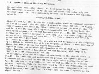
Re: frequency
As you can see, synching to WS at 44.1kHz (Grundig 9009 DEM cct applied to NON OS) has the DEM at 11.xkHz, (44.1/4) which is within the audio pass band.
Referring to the last couple of sentences in the attachment, it seems to follow that for up sampling in real time (PCM mode and PC playback) fDEM could be 192k x4, assuming the decoupling caps were appropriate.
Attachments
Last edited:
Thanks Ceglar,
Yes your right, John gave up also such circuits more jitter than working with a simple cap with a value near the theorical lock...
What is the best DEM cap value : 1 nF http://www.diyaudio.com/forums/digi...e-nos-dac-using-tda1541a-460.html#post3237091
o.r better to go with SSERG inputs with OSHIFIS DEM clock cap value : 456 pF for 176.4 Khz (4x Fws in NOS) ?
My understanding the last is best with 1 uF for DEM caps.
Atenuators circuits have been been gived up for ISS (no shunt résistors yet as Alexiis writed early (because bad)?! Need a source with 1.8 v for the TDA or resistors in serie for voltage attenuation if the source signal is > to 1.8 v ? No problem about the rise time with résistors ?
ALL the frequencies of the source if no Masterclock have to be multiple of 11.284Mhz if active divider... or equal or 2 x less ? The question is which source if no Ian's Fifo for source ? This last should be 44.1 Khz compatible ?
Does RyanJ go for the continuous gnd below the pcb but keeping the little divided routed gnd from John between the pins ?
Last edited:
Hi Eldam,
IIRC correctly, John had left one of the pins floating at some stage (10bit operation?) and at some other stage was synching to 44.1 which would have DEM operating at 44.1/4 with non-os, or maybe it was oversampling at 4x back then, I don't remember.
Anyway, I'd be looking for some direction from what the people who designed the chip had in mind.
On the board all you need is some pads at 16,17 which would allow for either DEM cap, or external circuit of users choice.
I don't know about the pro's and cons of different decoupling cap sizes to offer anything meaningful and same with the attenuators, except to say that some decided to use none at all (with 3.3V input) after trying it both ways.
With the core board you could use any I2S output source, most of them have two clocks to allow for all the usual sampling rates between 44.1 and 192k, and some up to 384k. WaveIO is well received, but then so are others.
I can't comment on PCB layout..
All to say, simple DEM cct with appropriate synch and frequency seems worth pursuing.
Regards,
Shane
I think this was from the auditions for Episode x+1, was on the 33rd day of the month IIRC.
Yeap. FAIL. He goofed on the hand-shake, after going through the whole "Is there no hope for the Widows Son?", thing.
(Hard to prove any lineage without a valid BC in any respect).
;-)
"If you see her, say hello.. she might be in Tangier…" ref: BD.
Yeap. FAIL. He goofed on the hand-shake, after going through the whole "Is there no hope for the Widows Son?", thing.
(Hard to prove any lineage without a valid BC in any respect).
;-)
"If you see her, say hello.. she might be in Tangier…" ref: BD.
Attachments

Last edited:
Obama Kenobi is very appreciate here in France : very class ! (elegant in the positiv way: à la MADMEN serie !) . On the photograph Is it a word from the masked boss of NSA whom put all the computers in the Black Stars... that's why Vader feels always the things before everybody ?
I send a PM to ZORRO VADER:
"Please gentle NSA's Vader_J (for Junior): any inputs about the old TDA1541? Could you please look at the computers of MR T. , MR John, Mr Pedja, put it in quantic computer to make us a good sounding DAC ? But at the price of Fanny-May (zero bucks) please ? Please avoid the EMC storms from the hands, Chip is fragile? but if you have a supplier for the same red soldering iron, it will be nice of you"
Last edited:
Member
Joined 2006
So far there are a number of great circuits with PCB designs presented, that could be fabricated into nice core boards when complete, which look quite promising.
In the meantime for those that are interested in getting the AYA II 2014 Edition PCB or kit, please click to this sign up page on the Pedja Rogic's website for the information on pricing and description.
AYA II 2014 DIY edition interest check - Audial online topic
You can also post your questions and comment for Pedja there.
Will open a group buy thread for it. Hope there is sufficient interest to get it going.
Btw, good star wars humor guys!
- Status
- This old topic is closed. If you want to reopen this topic, contact a moderator using the "Report Post" button.
- Home
- Source & Line
- Digital Line Level
- Any good TDA1541A DAC kit?