Ok, 10r resistors are everywhere, PSU wires + caps, DECOU caps and DEM cap are there too. Need some 100r for i/v and ground connections to start. Tomorrow i hope to run it ")
The 1541 doesn't have single direct connection - everything is thru resistors. It should "skew" the PSU voltages when powered on, based on current demand. By the way, would it oscillate in such case? I want to see "bare" unfiltered currents as worst-case scenario.
The 1541 doesn't have single direct connection - everything is thru resistors. It should "skew" the PSU voltages when powered on, based on current demand. By the way, would it oscillate in such case? I want to see "bare" unfiltered currents as worst-case scenario.
Hi,
If you cannot buy or have a 1X100 active probe, please make a suitable preamp and drop resistors to 0.1R...
Ciao T
Ok, 10r resistors are everywhere
If you cannot buy or have a 1X100 active probe, please make a suitable preamp and drop resistors to 0.1R...
Ciao T
Hi,
Personally I use a cascoded low capacitance J-Fet with a follower, bandwidth is something like 10MHz, depending on source impedance.
Just look at any wideband radio frequency stuff...
Ciao T
I haven't found any active probes which actually multiply/amplify, not to mention their price.
Preamp? Which suitable bandwidth is doable? FET, OpAmp based?
Personally I use a cascoded low capacitance J-Fet with a follower, bandwidth is something like 10MHz, depending on source impedance.
Just look at any wideband radio frequency stuff...
Ciao T
Hi T , with the 100uf/6.3v caps which way round are they connected acroos the resistor? IE does the negative of the cap go to the cathode or to the ADJ?Hi,
PS, connect 100uF/6.3V across the cathode to Adj resistor (R5, R7, R9, R13) to get the lowest possible impedance from the TL431, quality is not super critical, so no need to go Os-Con or Black Gate.
And if you replace the CS8412 with a CS8414 on adapter you should get a C0G 0603 SMD Cap (3300pF) and fit it directly at the CS8414 Pins and remove it from the main PCB. In fact I would probably move the whole set of parts on the FILT pin of the CS8412 to SMD and onto the adapter PCB.
C31, C36 and c39 are worth putting large values (small physical size) in place, C9, C11, C13 can use Elna Silmic.
Ciao T
Thanks,
Gordon
Hi,
Negative to adj of course. Also, watch the 6.3V rating if you happen to have more than 8.5V final DC across the 431. With 15V you need to use 16V/100uF.
Ciao T
Hi T , with the 100uf/6.3v caps which way round are they connected acroos the resistor? IE does the negative of the cap go to the cathode or to the ADJ?
Negative to adj of course. Also, watch the 6.3V rating if you happen to have more than 8.5V final DC across the 431. With 15V you need to use 16V/100uF.
Ciao T
Rargh, not yet investigated anything.
But kinda preview of what i have...
And again, i decided to go with CPLD on digital end to get more control on clocking, I2S etc.
What i want to do is feed the TDA in simultaneous mode. I'll halve the clock rates - therefore less disturbances, and ability to go 8x oversampling.
In addition, going CPLD brings possibility to use dufferent DF ICs which aren't compatible with 1541 by default. There are many nice DFs around which were no-no for 1541 due to their high BCLK rates.
I want to implement advanced clocking scheme, which will give ability to
- Slave/Master operation of SPDIF receiver
- OS/NOS operation
- Support of Hi-Rez 88.2, 96, 172.4, 192kHz formats falling back to NOS with DF bypass.
Moreover, dual-differential mode with two TDAs becomes possible as CPLD could split/invert the i2s to L+,L-, R+,R- signals, and pack each channel pair to single I2S line (or even simultaneous way).
That will require 2's compliment to binary offset conversions etc. The VHDL thing is pretty neat and new for me, and i like it. Tiny power, tiny footprint, flexibility and "hardcoded" design. I've already coded i2s inverter with two 32-bit arrays (shiftregs in hardware).
In addition, to futher reduce digital noise on DAC board, the reclocker should work with 3.3v levels - we don't need the 5v swing anyways, and working with 3.3v both reduces voltage swing, and slows down slew rate.
And best of all, the clock driver could be 5v, but with series-paralel termination dividing the signal in half, and bringing down the logic levels to 3.3v CMOS-compatible, with no reflections on either ends of transmission line.
The problem is... I have one quad DFF on the DAC for reclocking, but need to reclock 5 signals (data_L, data_R, BCLK, LRCLK, DEM_CLK). Argh, a bit on the FAIL side. Is there any TinyLogic (or comparable) DFFs which both have slow slew rates and differential outputs? I hate going the octal DFF ICs without differential outputs just to have an possibility to go simultaneous mode...
Attachments
Last edited:
Hi,
Yes, but the CPLD needed will create problems for most DIYérs.
Then you need to re-calculate the I2S attenuators.
So? Use a Hex or octal FF instead.
Ciao T
What i want to do is feed the TDA in simultaneous mode. I'll halve the clock rates - therefore less disturbances, and ability to go 8x oversampling.
Yes, but the CPLD needed will create problems for most DIYérs.
In addition, to futher reduce digital noise on DAC board, the reclocker should work with 3.3v levels - we don't need the 5v swing anyways, and working with 3.3v both reduces voltage swing, and slows down slew rate.
Then you need to re-calculate the I2S attenuators.
The problem is... I have one quad DFF on the DAC for reclocking, but need to reclock 5 signals (data_L, data_R, BCLK, LRCLK, DEM_CLK).
So? Use a Hex or octal FF instead.
Ciao T
Hi,
Yes, but the CPLD needed will create problems for most DIYérs.
I doubt whether DIYers will want to build my DAC
, but whenever they do - i can supply programmed CPLDs... I'm going with PLCC package and sockets, so DIYer could switch the programmed ICs or program 'em themselves, given the source is provided as well as compiled core and instructions. Programmer isn't that cheap (Xilinx SW compatible goes for ~$50, cheap alternative goes for ~$15)... CPLD ICs are around $2-$5, which isn't that bad given the possibilities they bring... JTAG connector will be there.I like the "single board fits all" thing, it seems i'll be able to make it compatible with most DACs around, both single and dual, and with different clocking schemes including ASRCs.
Shure, i'll tweak the attenuators/ slew rate filters in place and give appropriate values, as well as other circuit parts.Then you need to re-calculate the I2S attenuators.
I already had a bad time finding quad DFF with differential outputs.So? Use a Hex or octal FF instead.
Here are part numbers of "TinyLogic"-kind of devices with appropriate Q andQinv outputs. They need to be futher filtered for 5v-tolerant inputs and 3.3/5v Vcc operation.
NC7SP74*
NC7SV74*
NC7SZ74*
74LVC1G74*
74LVC2G74*
TC7WH74*
SN74LVC2G74*
But, prior to going with them, their layout in 2-sided (actually 1.5-sided) board should be reconsidered, as they require too many traces...
Ehm... I checked it. It seems unroutable in 1.5 layers without ruining CLK trace impedance. Paralel termination is a must in case of multipe inputs.
Going for single-ended DFF just because a feature of simultaneous input?
Hi,
Don't get me wrong, in AMR's commercial products we have been using CPLD's and FPGA's from Day one, it just erects a quite high barrier for access to most DIYérs...
With Diff outputs Quads are the max, AFAIK.
Bears consideration. All design is compromise.
Ciao T
I doubt whether DIYers will want to build my DAC
Don't get me wrong, in AMR's commercial products we have been using CPLD's and FPGA's from Day one, it just erects a quite high barrier for access to most DIYérs...
I already had a bad time finding quad DFF with differential outputs.
Here are part numbers of "TinyLogic"-kind of devices with appropriate Q andQinv outputs. They need to be futher filtered for 5v-tolerant inputs and 3.3/5v Vcc operation.
With Diff outputs Quads are the max, AFAIK.
Going for single-ended DFF just because a feature of simultaneous input?
Bears consideration. All design is compromise.
Ciao T
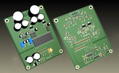
any experience/comment for this pcb? it looks very nice finishing
http://www.cdream5.com/htm/DAC1541A_2008.htm
http://www.cdream5.com/htm/DAC1541A_2008.htm
any experience/comment for this pcb? it looks very nice finishing
I used to own their TDA1540 board. The quality is good. They are finished boards. No assembly required. It worked straight away. I thought the sound was only good, but not great. I never bothered to modify or try to improve it.
I think the power supply is only a basic design, and the op amp output is not my cup of tea.
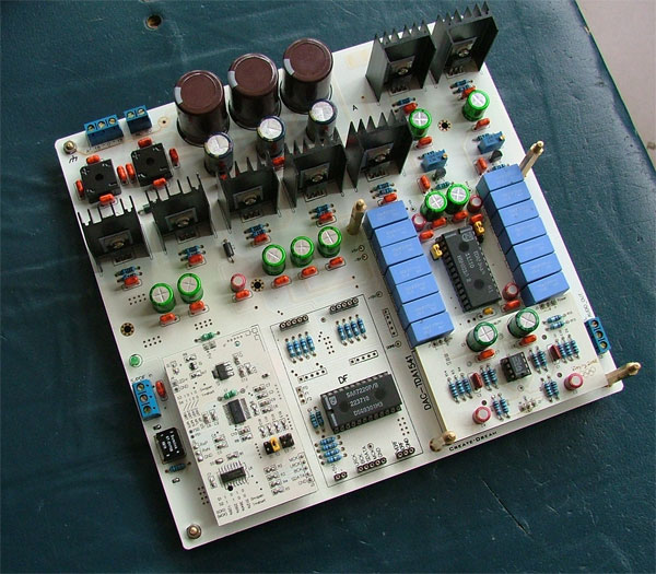
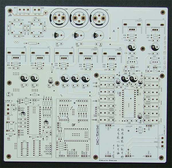
Nicely aligned components/blocks usually mean compromised performance. If the designer decided to go for a cool alingment instead of best performance... Then the board can't be good. Good electrical layout should look messy. It gets better with designer's experience, but never comes close to silly aligned components just like these seven yin yang caps aligned in a row - these could be placed closer to ICs. Much closer to supply pins. But then it wouldn't look so sweet and cool.
Some miss the meaning of "electronic design" thinking of word "design" as of visual art. It's not visual, it's electrical.
Some miss the meaning of "electronic design" thinking of word "design" as of visual art. It's not visual, it's electrical.
Last edited:
Nicely aligned components/blocks usually mean compromised performance. If the designer decided to go for a cool alingment instead of best performance... Then the board can't be good. Good electrical layout should look messy. It gets better with designer's experience, but never comes close to silly aligned components just like these seven yin yang caps aligned in a row - these could be placed closer to ICs. Much closer to supply pins. But then it wouldn't look so sweet and cool.
Some miss the meaning of "electronic design" thinking of word "design" as of visual art. It's not visual, it's electrical.
Fully agree there, looks like someone has been playing too much Tetris to me , haha.
But at least it has all of the stages seperate from each other on the PSU end, and relative physical seperation from each IC which lends itself to creative shielding using copper tape and walls made out of cardboard, I've seen other DAC Kits on ebay where the IC's were much closer to each other...
Last edited:
I have been for a while considering design choices and techniques for an "ultimate" design. AMR currently has other priorities, but a small "fanclub" project may be on the cards, sadly without accessing AMR's technolgy or resources, though the "rejects, leftovers and tangents" that I can use readily make for a lot of material to use.
I also have access to 4 or 6 layer Teflon & Ceramic PCB fabs for small runs.
PM me.
Ciao T
Thorsten, did this ever come off the ground?
Tried pm-ing you to no avail... Definately part of the fanclub!
- Status
- This old topic is closed. If you want to reopen this topic, contact a moderator using the "Report Post" button.
- Home
- Source & Line
- Digital Line Level
- Any good TDA1541A DAC kit?