Hi,
Any of them? Well, any with discrete Audio Clocks of suitable frequency.
You just need to remember to set your PC or player not to feed them anything else except 44.1KHz.
Why would it? Isolating I2S is trivial, given that most frequencies are quite low.
The AMR CD-77 CAN be used as Stand Alone DAC, so if I may be so bold, there is at least one.
Ciao T
Thanks but I am still not following. The USB2.0 asynch devices can't be isolated on the usb side even when running a 16/44.1 file, the required speed is still there independant of the audio, last I checked there were no 2.0 audioclass usb isolators.
Are you saying put the isolation on the clock? These almost all use 22.5792 mhz clocks for audio. We could put this clock at the DAC but what do you use to galvanically isolate going back to drive the usb chip ? I haven't seen a scheme for this sort of thing.
If someone has this working it would be quite nice I think and a boon for a lot of NOS tinkerers..
Hi,
Why do you keep going on about isolating USB?
Sure.
It varies, the XMOS reference design uses 11.XXX...
Well, how else would you do it? The circuitry is so primitive, so trivial, hence no-one has seen the need to elaborate.
There are so many isolators available that work fine at these speeds, just pick one. Many are BTW available with three lines one direction (I2S) and one line into the other (MCK).
Ciao T
Thanks but I am still not following. The USB2.0 asynch devices can't be isolated on the usb side even when running a 16/44.1 file, the required speed is still there independant of the audio, last I checked there were no 2.0 audioclass usb isolators.
Why do you keep going on about isolating USB?
Are you saying put the isolation on the clock?
Sure.
These almost all use 22.5792 mhz clocks for audio.
It varies, the XMOS reference design uses 11.XXX...
We could put this clock at the DAC but what do you use to galvanically isolate going back to drive the usb chip ? I haven't seen a scheme for this sort of thing.
Well, how else would you do it? The circuitry is so primitive, so trivial, hence no-one has seen the need to elaborate.
There are so many isolators available that work fine at these speeds, just pick one. Many are BTW available with three lines one direction (I2S) and one line into the other (MCK).
Ciao T
Is there any good TDA1541A DAC kit, on eBay or elsewhere?
This looks promising, and it has everything on a single PCB - good power supply, PCB layout looks good, it has NOS option, good I/V... I am very surprised that no one has mentioned this kit.... It seems like very good starting point, with all elements included -> so any further necessary tweaking could be easily executed. I always preferred “everything” on a single PCB, compared to 3, 4 or 5 separate modules that need to be connected together to get a fully working DAC.
The only thing that’s missing is USB (and TORX….)
Boky
Which kit are you referring to?
Hi,
On first looks - train wreck...
Ciao T
On first looks - train wreck...
Ciao T
This looks promising …
"Looks promising" is meaningless to me. I'm looking for a kit which is known to be of excellent results.
On first looks - train wreck...
That's what I was looking for all along…
")
Raindrop_hui is kown to be skittish with her designs.
They're not her designs - she's only selling them. The designer is a guy who takes relatively little interest in how they sound. As such they're reasonable points of departure for modders.
Folks,
Okay, lets do some analysis of the kit from pictures, shall we?
First, one quick look suffices to note that this "kit" is mostly a "cut'n'paste" job from a number of sources, not something that I would call a "design".
Let's start at the beginning. The WM8805 circuitry is "bog standard". But the decoupling, instead of following best practice, is based on audiophoolish notions of using through hole film cap's with arrangements that produce long loops on chips that run at frequencies of 10's of MHz all the way to around 100MHz (WM8805 internal operation). The powersupply are generic 3-Pin regulators, including for the critical reference clock for the DPLL in the WM8805.
The "Os-Con's" may look similar to the best series from Sanyo but are the cheaper Nichicon alternative. I have tested these myself and they perform anywhwere between three times (resonance frequency) and twenty times (minimum impedance) worse than real Os-Cons.
So the WM8805 section will work after a fashion, but there is no way it is ever going to offer anything like the phase-noise / jitter levels the WM8805 is capable of. In fact, I think despite all it's shortcomings, a well applied Cirrus Logic CS-8412/14 will have lower jitter.
Okay, the SAA7220 is a MASSIVE noise generator. It's decoupling matches that of the rest of the digital section, that is it has for all intents grassmudhorse all decoupling. The single ferrite bead between the SAA7220 PSU will help, but likely not remotely enough, especially as the "far side" of it is not decoupled...
Just poking a 'scope around the PSU pins on this PCB will be feast for the eyes, I'd predict noise levels in the 100's of mV around the filter and probably no better for the rest.
Okay, now our heavily jittered signal goes to our TDA1541.
This has the same kind of decoupling arrangements on the supplies as the rest of digital section, that is grassmudhorse incompetent and the DEM decoupling is about as bad as can be.
By the looks of it the regulators for the TDA1541's are some discrete ones, does not like shunts though. No matter how good or bad they are, they are too far from the IC's to do much good no matter their nature.
Overall the level of "engineering" around the TDA1541's seems an attempt to recreate the 1980's Philips/Marantz approache and getting an epic FAIL at even that task (I would recommend these players primarily as a lesson in "how not to do it").
Okay on to the analogue stages. These seem a mixture out of one of the common base I/V's we have seen here (there where numerous variation on these all with noisy LEDS's as references), I'd probably rather have a CEN or SEN, but they are probably the part of the whole circuit, thanks to the Chinese Kopy-Mao that calls itself "Engineer" having used a rather decent source to Kopy.
Sadly the Kompetence of the Kopy-Mao did not extend to kopying a discrete diamond buffer to place after the I/V so we find an Op-Amp.
I think almost anyone can build a better TDA1541 DAC on a piece of veroboard and using some copper foil, using what can be learned in the forums here.
Certain the "Reference" DIYA Groupbuy project would be a better choice, wretched as it is...
That's not just a trainwreck, that's an epic, high speed, Wenzhou level trainwreck, complete with completely clueless Wang Yongping style apologists saying "This is all very good and proper, whether or not you believe, I believe it."
CAVEAT EMPTOR MONITUS ES
Ciao T
On first looks - train wreck...
Okay, lets do some analysis of the kit from pictures, shall we?
First, one quick look suffices to note that this "kit" is mostly a "cut'n'paste" job from a number of sources, not something that I would call a "design".
Let's start at the beginning. The WM8805 circuitry is "bog standard". But the decoupling, instead of following best practice, is based on audiophoolish notions of using through hole film cap's with arrangements that produce long loops on chips that run at frequencies of 10's of MHz all the way to around 100MHz (WM8805 internal operation). The powersupply are generic 3-Pin regulators, including for the critical reference clock for the DPLL in the WM8805.
The "Os-Con's" may look similar to the best series from Sanyo but are the cheaper Nichicon alternative. I have tested these myself and they perform anywhwere between three times (resonance frequency) and twenty times (minimum impedance) worse than real Os-Cons.
So the WM8805 section will work after a fashion, but there is no way it is ever going to offer anything like the phase-noise / jitter levels the WM8805 is capable of. In fact, I think despite all it's shortcomings, a well applied Cirrus Logic CS-8412/14 will have lower jitter.
Okay, the SAA7220 is a MASSIVE noise generator. It's decoupling matches that of the rest of the digital section, that is it has for all intents grassmudhorse all decoupling. The single ferrite bead between the SAA7220 PSU will help, but likely not remotely enough, especially as the "far side" of it is not decoupled...
Just poking a 'scope around the PSU pins on this PCB will be feast for the eyes, I'd predict noise levels in the 100's of mV around the filter and probably no better for the rest.
Okay, now our heavily jittered signal goes to our TDA1541.
This has the same kind of decoupling arrangements on the supplies as the rest of digital section, that is grassmudhorse incompetent and the DEM decoupling is about as bad as can be.
By the looks of it the regulators for the TDA1541's are some discrete ones, does not like shunts though. No matter how good or bad they are, they are too far from the IC's to do much good no matter their nature.
Overall the level of "engineering" around the TDA1541's seems an attempt to recreate the 1980's Philips/Marantz approache and getting an epic FAIL at even that task (I would recommend these players primarily as a lesson in "how not to do it").
Okay on to the analogue stages. These seem a mixture out of one of the common base I/V's we have seen here (there where numerous variation on these all with noisy LEDS's as references), I'd probably rather have a CEN or SEN, but they are probably the part of the whole circuit, thanks to the Chinese Kopy-Mao that calls itself "Engineer" having used a rather decent source to Kopy.
Sadly the Kompetence of the Kopy-Mao did not extend to kopying a discrete diamond buffer to place after the I/V so we find an Op-Amp.
I think almost anyone can build a better TDA1541 DAC on a piece of veroboard and using some copper foil, using what can be learned in the forums here.
Certain the "Reference" DIYA Groupbuy project would be a better choice, wretched as it is...
That's not just a trainwreck, that's an epic, high speed, Wenzhou level trainwreck, complete with completely clueless Wang Yongping style apologists saying "This is all very good and proper, whether or not you believe, I believe it."
CAVEAT EMPTOR MONITUS ES
Ciao T
That's what I was looking for all along…
I played a lot with 1541 and built few DAC's with this chip...and gained reasonable experience....you can do the search on these forums using ‘1541’ and ‘Extreme_Boky’ to find out much more info on proper 1541 implementation than you are getting here from people who are trying to sell you their products .... and are advertising for free.
The Chinese kit has everything done quite OK for the price.... and it can serve as an excellent learning project. What I see is a complete plug-n-play DAC that has all important components of the design done right, and it could sound very good. Once YOU learn / figure-out what good 1541 implementation is, you can make your own educated decision.
If you want really good complete DAC solution with 1541... you'll have to wait a bit longer because there is none on the market at the moment.
Boky
Hi,
So have I. Since 1998.
And with many other chips besides the TDA1541 since before 98...
My very first TDA1541 one was already WAY and mean WAY past this kit in terms of implementation.
By now I'm probably up to generation X on numbering and somehow I notice that John Brown's and my own designs seem to converge on many of the same solutions...
If you want to know how the TDA1541 should be decoupled much good information can be found in ecdesigns thread.
I have no interest getting into slagging matches and I have nothing TDA1541 related to sell that anyone here at diya would buy.
I would however recommend doing the precise search Extreme_Boky has suggested (I just did ) and then evaluate his claims against the results of this search. You may also find this little diversion below amusing...
Extreme_Boky 1541 / Loesch 1541 - Google Fight : make this fight with googlefight !
So, you recommend the kind of layout and power supply decoupling used in this kit? You would apply the same yourself? Good luck.
Really!
I shall look greatly forward to your design effort. Things have been a bit grim around here in recent times and any diversion is welcome...
Ciao T
I played a lot with 1541 and built few DAC's with this chip...
So have I. Since 1998.
And with many other chips besides the TDA1541 since before 98...
My very first TDA1541 one was already WAY and mean WAY past this kit in terms of implementation.
By now I'm probably up to generation X on numbering and somehow I notice that John Brown's and my own designs seem to converge on many of the same solutions...
If you want to know how the TDA1541 should be decoupled much good information can be found in ecdesigns thread.
you can do the search on these forums using ‘1541’ and ‘Extreme_Boky’ to find out much more info on proper 1541 implementation than you are getting here from people who are trying to sell you their products
I have no interest getting into slagging matches and I have nothing TDA1541 related to sell that anyone here at diya would buy.
I would however recommend doing the precise search Extreme_Boky has suggested (I just did
) and then evaluate his claims against the results of this search. You may also find this little diversion below amusing...Extreme_Boky 1541 / Loesch 1541 - Google Fight : make this fight with googlefight !
The Chinese kit has everything done quite OK for the price.... and it can serve as an excellent learning project.
So, you recommend the kind of layout and power supply decoupling used in this kit? You would apply the same yourself? Good luck.
What I see is a complete plug-n-play DAC that has all important components of the design done right
Really!
If you want really good complete DAC solution with 1541... you'll have to wait a bit longer because there is none on the market at the moment.
I shall look greatly forward to your design effort. Things have been a bit grim around here in recent times and any diversion is welcome...
Ciao T
Hi,
Okay, talking about copper foil, veroboard and all...
1) The actual circuit design for TDA1541A
First, if one designs a commercial product it is possible to do a lot of development and a lot of work that is not really amenable to the average DIY'er.
For example, the I2S attenuators for the TDA1541 (yes, we where doing them in 2005) are based around SMD CMOS to PECL drivers, with a temperature compensated powersupply and a very minimal voltage swing (it does make a difference). Even with a full set of schematics this kind of circuit would prove to be difficult to get right in terms of layout and all other factors.
So my first recommendation is to use circuitry that is "diy-friendly", which means simple.
There are some circuits we need to consider.
One of the areas where we can really gain over generica is with DEM reclocking and I2S Attenuators. For this my recommendation would be to use the classic, simple passive I2S attenuators and direct resistive DEM reclocking John Brown (ecdesigns) kindly shared with the diya community.
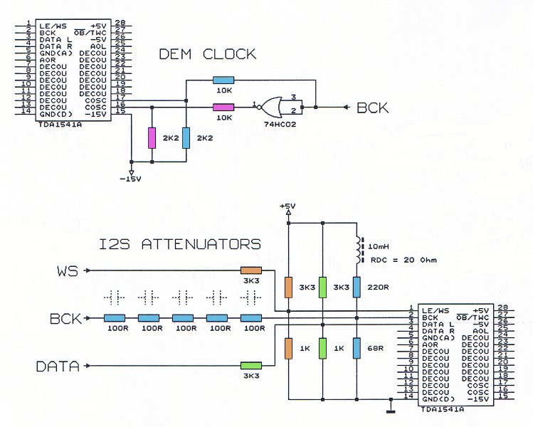
For simplicity, use a 74HC4040 to divide BCK (which will be between 32 and 64Fs depending on your precise source) down for the DEM reclocker so you get between 4 and 8 Fs for the reclock, other frequencies do work, but can be tricky to get to work reliably, let's walk before we run.
This can be optimised a lot more, but to be honest, it works very well and is easy to apply, the jump from "bog standard" to this configuration is by far larger than from this to a major optimised version.
In front of the I2S attenuator place a reclocker.
There is some major debate here and ideally we would be using seperate reclocker IC's for each and every line, ideally with daisy chained flip flops from one 74HC74 IC. While I do not as such disagree, this solution is not very diy friendly. Plus, using three IC's instead of one increases the clock load for the system clock, you win some you loose some.
So I would use a multi-flipflop reclocker instead, a 74HC175 is a quad, allowing us also to reclock the divided down BCK for the DEM reclocking. So the 74HC4040 is connected from the BCK in front of the re-clocker.
With the 74HC175 we have both inverted and non-inverted outputs, so we can drive the DEM reclocker directly, no extra inverters needed. As the I2S attenuator circuit will pose a load onto the reclocker IC (and through it on the supply) it is best to add the same components to the unused output, where they balance the load, so we do not see any PSU load change if the outputs change state.
IC use is modest, just a 74HC175 reclocker and a 74HC4040 as divider for the DEM Clock in front of the TDA1541.
Having now all and sundry clocks, data etc. entering the TDA1541 marching in German Wehrmacht Lockstep, at reasonably close to optimum levels for the TDA1541 internal logic as well, we can move on.
In front of this reclocker we may add any kind of I2S source we like. If there is a decently designed WM8805 based board around this would be my choice or any of the Async USB Audio Solutions if we desire PC interfacing. The reclocker will take care of the level shifting from 3.3V to 5V needed for the I2S attenuators. A CD drive can also be used, take your pick.
Okay, next stop, DEM Decoupling, the capacitors should be small size, surface mount and Film. There are now many such options, 0.1uF is minimum value recommended, bigger can work, but avoid physically big cap's.
For the TDA1541 ONLY we can also use these SMD film cap's for the PSU rail decoupling. At the worst it will see around 6MHz clocks AND because the TDA1541 internally uses current steering (a non-standard ECL Logic essentially), so there is much less RF in the PSU Rails we need to decouple.
I personally would add also Elna Silmic cap's on the DAC rails and use larger value film Cap's added to the MSB DEM decoupling Pins, or even Os-Con's (as for the MSB only any leakage in the cap will only change the overall level.
Now power supplies. I would suggest using shunt regulators, however the important part is that shunt section is close to the TDA1541. Feed them from current sources, which can be remote and add a choke before the Shunt Reg.
There are many options, take your pick. I used TL431's on many of my DAC's and they work well, are compact and easily applied. But they can be bettered quite easily, but with more complexity. Similar tradeoff's apply to current sources.
Again, the shunt regulator (whatever you end up using) is really only worth having if you can get right up close to the IC, the CCS can be placed as you like. If you do not get the Shunt close to the supplied circuit you might as well use a LM317 Chip reg.
Use a completely separate set of windings or even transformer to generate the supplies for the TDA1541. You can use two windings to generate +/- for the TDA1541, no need for three, more interesting arrangements may be applied for those who know how to do it...
Use another windings rectifier and associated misellania and regulator only for the reclocker. Give the reclocker the best decoupling you can, 0603 SMD Capacitors into a groundplane is really recommended on top of bigger bypasses. Use an extra shunt / ccs to produce the supply for the I2S Attenuators, but you can share the raw supply with the reclocker.
Have another separate supply for the rest of the logic, you can share this with the rest of the source, use a choke and some sensible decoupling though.
The clock in the source that eventually feeds the reclocker should have a very good, fully separate supply with very low noise.
Add an analogue stage to taste, I'd probably try a CEN right now, for fun, or use my "final" tube stage instead, Lukasz Fikus's design is an option too, you can even use Op-Amp's or anything you fancy.
In fact, the above describes quite well the TDA1541 DAC that now plays in my system. Source is still a CS8414 with some trick circuitry, tube stage using a 6072A...
Okay, this concludes part one, I'll talk about how to approach getting all the above onto a piece of veroboard with nice copper foil (silver for anyone who is thusly inclined) ground planes when I next find time.
Ciao T
I think almost anyone can build a better TDA1541 DAC on a piece of veroboard and using some copper foil, using what can be learned in the forums here.
Okay, talking about copper foil, veroboard and all...
1) The actual circuit design for TDA1541A
First, if one designs a commercial product it is possible to do a lot of development and a lot of work that is not really amenable to the average DIY'er.
For example, the I2S attenuators for the TDA1541 (yes, we where doing them in 2005) are based around SMD CMOS to PECL drivers, with a temperature compensated powersupply and a very minimal voltage swing (it does make a difference). Even with a full set of schematics this kind of circuit would prove to be difficult to get right in terms of layout and all other factors.
So my first recommendation is to use circuitry that is "diy-friendly", which means simple.
There are some circuits we need to consider.
One of the areas where we can really gain over generica is with DEM reclocking and I2S Attenuators. For this my recommendation would be to use the classic, simple passive I2S attenuators and direct resistive DEM reclocking John Brown (ecdesigns) kindly shared with the diya community.
For simplicity, use a 74HC4040 to divide BCK (which will be between 32 and 64Fs depending on your precise source) down for the DEM reclocker so you get between 4 and 8 Fs for the reclock, other frequencies do work, but can be tricky to get to work reliably, let's walk before we run.
This can be optimised a lot more, but to be honest, it works very well and is easy to apply, the jump from "bog standard" to this configuration is by far larger than from this to a major optimised version.
In front of the I2S attenuator place a reclocker.
There is some major debate here and ideally we would be using seperate reclocker IC's for each and every line, ideally with daisy chained flip flops from one 74HC74 IC. While I do not as such disagree, this solution is not very diy friendly. Plus, using three IC's instead of one increases the clock load for the system clock, you win some you loose some.
So I would use a multi-flipflop reclocker instead, a 74HC175 is a quad, allowing us also to reclock the divided down BCK for the DEM reclocking. So the 74HC4040 is connected from the BCK in front of the re-clocker.
With the 74HC175 we have both inverted and non-inverted outputs, so we can drive the DEM reclocker directly, no extra inverters needed. As the I2S attenuator circuit will pose a load onto the reclocker IC (and through it on the supply) it is best to add the same components to the unused output, where they balance the load, so we do not see any PSU load change if the outputs change state.
IC use is modest, just a 74HC175 reclocker and a 74HC4040 as divider for the DEM Clock in front of the TDA1541.
Having now all and sundry clocks, data etc. entering the TDA1541 marching in German Wehrmacht Lockstep, at reasonably close to optimum levels for the TDA1541 internal logic as well, we can move on.
In front of this reclocker we may add any kind of I2S source we like. If there is a decently designed WM8805 based board around this would be my choice or any of the Async USB Audio Solutions if we desire PC interfacing. The reclocker will take care of the level shifting from 3.3V to 5V needed for the I2S attenuators. A CD drive can also be used, take your pick.
Okay, next stop, DEM Decoupling, the capacitors should be small size, surface mount and Film. There are now many such options, 0.1uF is minimum value recommended, bigger can work, but avoid physically big cap's.
For the TDA1541 ONLY we can also use these SMD film cap's for the PSU rail decoupling. At the worst it will see around 6MHz clocks AND because the TDA1541 internally uses current steering (a non-standard ECL Logic essentially), so there is much less RF in the PSU Rails we need to decouple.
I personally would add also Elna Silmic cap's on the DAC rails and use larger value film Cap's added to the MSB DEM decoupling Pins, or even Os-Con's (as for the MSB only any leakage in the cap will only change the overall level.
Now power supplies. I would suggest using shunt regulators, however the important part is that shunt section is close to the TDA1541. Feed them from current sources, which can be remote and add a choke before the Shunt Reg.
There are many options, take your pick. I used TL431's on many of my DAC's and they work well, are compact and easily applied. But they can be bettered quite easily, but with more complexity. Similar tradeoff's apply to current sources.
Again, the shunt regulator (whatever you end up using) is really only worth having if you can get right up close to the IC, the CCS can be placed as you like. If you do not get the Shunt close to the supplied circuit you might as well use a LM317 Chip reg.
Use a completely separate set of windings or even transformer to generate the supplies for the TDA1541. You can use two windings to generate +/- for the TDA1541, no need for three, more interesting arrangements may be applied for those who know how to do it...
Use another windings rectifier and associated misellania and regulator only for the reclocker. Give the reclocker the best decoupling you can, 0603 SMD Capacitors into a groundplane is really recommended on top of bigger bypasses. Use an extra shunt / ccs to produce the supply for the I2S Attenuators, but you can share the raw supply with the reclocker.
Have another separate supply for the rest of the logic, you can share this with the rest of the source, use a choke and some sensible decoupling though.
The clock in the source that eventually feeds the reclocker should have a very good, fully separate supply with very low noise.
Add an analogue stage to taste, I'd probably try a CEN right now, for fun, or use my "final" tube stage instead, Lukasz Fikus's design is an option too, you can even use Op-Amp's or anything you fancy.
In fact, the above describes quite well the TDA1541 DAC that now plays in my system. Source is still a CS8414 with some trick circuitry, tube stage using a 6072A...
Okay, this concludes part one, I'll talk about how to approach getting all the above onto a piece of veroboard with nice copper foil (silver for anyone who is thusly inclined) ground planes when I next find time.
Ciao T
Hi,
So have I. Since 1998.
And with many other chips besides the TDA1541 since before 98...
My very first TDA1541 one was already WAY and mean WAY past this kit in terms of implementation.
By now I'm probably up to generation X on numbering and somehow I notice that John Brown's and my own designs seem to converge on many of the same solutions...
If you want to know how the TDA1541 should be decoupled much good information can be found in ecdesigns thread.
I have no interest getting into slagging matches and I have nothing TDA1541 related to sell that anyone here at diya would buy.
I would however recommend doing the precise search Extreme_Boky has suggested (I just did
Extreme_Boky 1541 / Loesch 1541 - Google Fight : make this fight with googlefight !
So, you recommend the kind of layout and power supply decoupling used in this kit? You would apply the same yourself? Good luck.
Really!
I shall look greatly forward to your design effort. Things have been a bit grim around here in recent times and any diversion is welcome...
Ciao T
Chinese DAC is not bad to the extent you’d like it be. It has solid ground plane topology around digital section that can be used to further improve the performance of the whole DAC. You referred to 7220 upsampling chip and levels of noise…. EVERY upsampler is the noise generator. I rank them as noise issue No1 inside dig to analog conversion box, that being either DAC or CD player. The microcontroller chip is close second…. But, the 7220 chip will provide NOS/OS option, so at least there’s something to try that other 1541 kits do not offer. If NOS is preferred, I think the 7220 can be completely removed. Also, the ground plane noise around digital section can be reduced. This will provide the most important learning curve path: how to reduce power supply noise around noisiest chip – the 7220, by implementing proper decoupling technics…. Same can be applied to 1541’s and one may end up with properly decoupled design. Soon after this, the need of completely different ground plane design may be required as the only option to further reduce noise around digital chips… Once at this level of understanding and knowledge, the educated decision can be made as to which DAC kit offers such option on the market at the moment. I could not find any such kit on the current market. Maybe you can….?
The Chinese DAC kit has all necessary sections included on the single board at very reasonable price and for that reason alone is worth of serious consideration by anyone who wants to play with 1541 chip, as opposed to many kit offerings that consist of 2, 3 or more modules, which seriously compromise ground uniformity, so all your comments from previous posts simply don’t apply and are completely useless and out of context. Your suggestion is a DAC chip on a single, stand-alone board…??? How many extra modules will be needed to get even close to Chineese DAC kit solution???? And, how much would your “modular” solution cost???? And, the final question for you, the expert: do you seriously think that modular solution will obtain lower levels of noise compared to Chineese DAC ?????
Boky
Hi,
I'd like to be good, expect it is not.
Hold it, you mean the DAC needs to be improved?
I disagree, as said. Almost anyone can do better using veroboard.
I have no idea what you are talking about.
I am not advocating a modular solution, but rather suggest that one may use whatever is desired as source. There is no need to to design this part in, a correctly implemented set of connections are fine.
As to how much would it cost? The parts, the vero board and less time than you would need to fix the china DAC, if you actually could, which you cannot without massively hacking up the PCB...
Looking at design of the chinese DAC, yes absolutely.
And much lower jitter too. With a CS8414 receiver as well...
Ciao T
Chinese DAC is not bad to the extent you’d like it be.
I'd like to be good, expect it is not.
This will provide the most important learning curve path: how to reduce power supply noise around noisiest chip – the 7220, by implementing proper decoupling technics….
Hold it, you mean the DAC needs to be improved?
The Chinese DAC kit has all necessary sections included on the single board at very reasonable price and for that reason alone is worth of serious consideration by anyone who wants to play with 1541 chip
I disagree, as said. Almost anyone can do better using veroboard.
Your suggestion is a DAC chip on a single, stand-alone board…??? How many extra modules will be needed to get even close to Chineese DAC kit solution???? And, how much would your “modular” solution cost????
I have no idea what you are talking about.
I am not advocating a modular solution, but rather suggest that one may use whatever is desired as source. There is no need to to design this part in, a correctly implemented set of connections are fine.
As to how much would it cost? The parts, the vero board and less time than you would need to fix the china DAC, if you actually could, which you cannot without massively hacking up the PCB...
And, the final question for you, the expert (ha!): do you seriously think that your modular solution will obtain lower levels of noise compared to Chineese DAC ?????
Looking at design of the chinese DAC, yes absolutely.
And much lower jitter too. With a CS8414 receiver as well...
Ciao T
I would deffer that to you, being closer of themThey're not her designs - she's only selling them. The designer is a guy who takes relatively little interest in how they sound. As such they're reasonable points of departure for modders.
I saw the producs only on pictures on eBAy and was striked by the "do not dare to copy me" note on all of them.@Extreme_Boky
Some of the "improvements"peddled around here by some that have commerical interests (like DEM reclocking) look good on paper but I didn't saw any proof that they really make a difference.
Except the statemens about "Philips, Denon, Marantz engineers where all lame". In my country we say "when two people say you are drunk, go to bed". When you try to say that 10-20 engineers, in 5-10 different companies, on 3-4 continents are all lame... maybe they are not the problem.
Last edited:
ThorstenL said:Now power supplies. I would suggest using shunt regulators, however the important part is that shunt section is close to the TDA1541. Feed them from current sources, which can be remote and add a choke before the Shunt Reg.
I take it this would imply you don't see any need to "degenerate" the current sources for flat impedance across the audio band? Then again from the TDA's point of view they would appear in parallel with the shunts and be pretty much invisible either way.
Last edited:
Hi,
Get an AP-2, a bunch of chips and test them with/without DEM reclocking (low and high level distortion).
The I2S attenuators can be seen in the jitter measurements.
Funnily enough Philips documentation shows DEM reclocking and for example the DA-12/LHH-1000 has a lot of interesting design details that show that these Engineers knew very well what they where doing, but elected to not apply this knowledge in all but the absolute top of the line stuff.
The DA-12 has even got a secondary PLL with a discrete low noise oscillator.
Well, given that you are the one saying this, maybe you should take your own advise...
Ciao T
Some of the "improvements" like DEM reclocking sound good on paper but I didn't see any proof that they really make a difference.
Get an AP-2, a bunch of chips and test them with/without DEM reclocking (low and high level distortion).
The I2S attenuators can be seen in the jitter measurements.
Except the lame "Philips, Denon, Marantz engineers where all lame".
Funnily enough Philips documentation shows DEM reclocking and for example the DA-12/LHH-1000 has a lot of interesting design details that show that these Engineers knew very well what they where doing, but elected to not apply this knowledge in all but the absolute top of the line stuff.
The DA-12 has even got a secondary PLL with a discrete low noise oscillator.
In my country we say "when two people say you are drunk, go to bed". When you try to say that 10-20 engineers, in 5-10 different companies, on 3-4 continents are all lame... maybe they are not the problem.
Well, given that you are the one saying this, maybe you should take your own advise...
Ciao T
- Status
- This old topic is closed. If you want to reopen this topic, contact a moderator using the "Report Post" button.
- Home
- Source & Line
- Digital Line Level
- Any good TDA1541A DAC kit?