Hi Andrea,
Whats the voltage developing across without the resistor in place?.. assuming its not just a simple matter of omitting the I/V resistor (given the cct, it simply cant be), is the replacement device considered linear?.
Regards,
Shane
The voltage developed at the output of the DAC (TDA1541A) is around +/-2mV (+/-2mA/1 ohm).
The tube named THE QUEEN is the most linear tube I have measured with a curve tracer. So the simulated distortion of this circuit is less than 0.01%.
Andrea
Better without I/V resitor then feeding a first high gain tubes before an other one for buffer ? that's the goal or is it better to use the theoric low value around 32 ohms and then less gain ?
Shane, you use a not wirewound but carbon resistor here IIRC ?
How is your best tubes circuit in the relation to the OPA861 outputstages (still use the two 4.7 uf Black Gate N here when you populated the kit some years ago ?
I'd like to use a discrete CEN with low noise linear reg (because high voltage... I'm a galic, I'm afraid of the storm and the lightenings ! ) Still valid these tubes circuit with the modern tubes and the expensive output transformer or teflon caps ?
The voltage developed at the output of the DAC (TDA1541A) is around +/-2mV (+/-2mA/1 ohm).
The tube named THE QUEEN is the most linear tube I have measured with a curve tracer. So the simulated distortion of this circuit is less than 0.01%.
Andrea
The signal at the output of the chip with full scale input is 4mAp-p centred at zero volts.
Where do you get the 1ohm from, unless you put it there?.
Shane, you use a not wirewound but carbon resistor here IIRC ?
How is your best tubes circuit in the relation to the OPA861 outputstages (still use the two 4.7 uf Black Gate N here when you populated the kit some years ago ?
I'd like to use a discrete CEN with low noise linear reg (because high voltage... I'm a galic, I'm afraid of the storm and the lightenings ! ) Still valid these tubes circuit with the modern tubes and the expensive output transformer or teflon caps ?
Hi Damien,
I tried those 33ohm TX-2575 and 39ohm old stock Shinkoh Tantalum 2W (parts connexion has some), and preferred Tantalum. The tube stage itself does use carbon composite resistors elsewhere..
The OPA861 as supplied in AYA II came with 47uF/6.3 BG Hi-Q NX final shunt caps on the +/- supplies. Also AB 1k2 I/V in-between the OPA861 trans. amp and the buffer. This is with the CCS injection scheme where you can null for 0mV (practically - although it does wander with heat) at either the output of the chip, or at the output of the OPA861.. which is pretty cool because you can then DC couple into the next stage (pre amp, amp, wax coil head cutting amplifier?).
It was better than WE396A CCS loaded (Pimm v5) parafeed into TX-102mk3 from S&B.
When Thorsten suggested to remove the current injection and then bias the tube using the current offset from the D/A itself, I tried 6922, 6072 and E180F/d3A. All were better than the previous RC biased WE396A, and also better than the OPA861 cct, with or without the second OPA861 buffer.
D3A would likely work very well as a grounded grid stage, with such high Gm driving the cathode would present input impedance of 1/Gm, however output impedance would be higher than I'd like it to be for how I am using it.
I sort of gave up listening about all the voltage compliance thing 25mV after hearing CD-77, and then reading about some distortion analysis (independent from AMR), and then finally again after building and listening. From what I have learned, using a 'faster' sounding tube makes it sound 'less slow'

hope this helps..
Shane
The signal at the output of the chip with full scale input is 4mAp-p centred at zero volts.
Where do you get the 1ohm from, unless you put it there?.
The CCS set the DAC output at 0 volt, so the signal swings +/- 2mA.
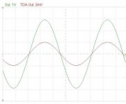
1 ohm is the impedance seen from the DAC, since there is no IV resistor and the DAC see a grounded grid stage with very low input impedance (see point named TDA Out)
Attachments
The CCS set the DAC output at 0 volt, so the signal swings +/- 2mA.
1 ohm is the impedance seen from the DAC, since there is no IV resistor and the DAC see a grounded grid stage with very low input impedance (see point named TDA Out)
Thanks Andrea, but which grounded grid stage are we talking about?..
TDA OUT = 2mVAC signal output is that peak to peak?
Last edited:
Thanks Andrea, but which grounded grid stage are we talking about?..
TDA OUT = 2mVAC signal output is that peak to peak?
The signal is taken in the cathode circuit, as in a typical grounded grid stage, that guarantees low input impedance. Then the V2 tube shift the reference of V1 grid following the input signal. Due to the very high gain of the two stage the final input impedance is around 1 ohm.
The TDA swings from 0 to -4mA, but since the servo set its output to 0V, the voltage developed across its output is +/- 2mV (+/- 2mA / 1 ohm).
I'm not sure I understand..
If the input impedance of a grounded grid stage is approx 1/Gm a high Gm tube like d3A with 30 to 40mA/V.. the input impedance would be 1/0.035 = 28 ohms?.
6C45 50mA/V = 20 ohm?
Pedjas OPA861 follows similar principle driving the emitter, for input impedance ~10ohm.
If the input impedance of a grounded grid stage is approx 1/Gm a high Gm tube like d3A with 30 to 40mA/V.. the input impedance would be 1/0.035 = 28 ohms?.
6C45 50mA/V = 20 ohm?
Pedjas OPA861 follows similar principle driving the emitter, for input impedance ~10ohm.
Last edited:
Hi, I am thinking of using Ians Fifo to feed this. Do I need the I2S to PCM, or will the Fifo feed a NOS tda1541?
Another thing Im not sure about is, should I just get a wavio usb to feed the tda1541 directly. All my music these days is computer based. Whats the best way to feed my dac?
Another thing Im not sure about is, should I just get a wavio usb to feed the tda1541 directly. All my music these days is computer based. Whats the best way to feed my dac?
Hey Luke,
You don't "need" the I2S to PCM board to run NOS from the fifo. You NEED the I2S to PCM board to run simultaneous feed to the dac, and by need I mean need. It sounds very gooder.....
Try a rasb pi feeding the fifo, this can use volumio or rune or another os to run music off the hdd over ethernet. Make sure you get rev B with the P5 header.
You decide if you like the dual clock board or the si570, ask on the thread as to the flavors of each.
Chuz,
Drew.
Last edited:
I'm not sure I understand..
If the input impedance of a grounded grid stage is approx 1/Gm a high Gm tube like d3A with 30 to 40mA/V.. the input impedance would be 1/0.035 = 28 ohms?.
6C45 50mA/V = 20 ohm?
Pedjas OPA861 follows similar principle driving the emitter, for input impedance ~10ohm.
The V1 tube has a mu around 300, the lowest possible input impedance would equal rp/mu²
You can find the theory of operation in Broskie's website
Broskie I-to-V
I replaced the V1 tube with a very high transconductance one.
The calssic DC servo was replaced with a voltage controlled CCS.
The plot of the signals at the input and output of the circuit is from a simulation, but the model of the tube V1 is from a real measurement with a curve tracer.
Hi fellows,
As a logical and natural continuation of the good enough kit part of this thread and as we need also an input stage to have a whole "good enough kit" I open a thread for beginners and low brained Wookies.
It's about to understand how to choose an input stage for the TDA1541 and what are the different option involved in the Distinctive TDA1541 coreboard as the AYA2 2014 revision board (with this last limited edition, P. Rodjic put 4 uf.l connectors and a switch also to allow more choice than its 2008 spidf and USB stages).
simple I2S as simultanous mode are mentioned.
link : http://www.diyaudio.com/forums/digi...ts-tda1541-understanding-non-specialists.html
I hope we will have in the same spirit as here the help of the cleverest fellows as the good willed ones.
Cheers
The V1 tube has a mu around 300, the lowest possible input impedance would equal rp/mu²
You can find the theory of operation in Broskie's website
Broskie I-to-V
I replaced the V1 tube with a very high transconductance one.
The calssic DC servo was replaced with a voltage controlled CCS.
The plot of the signals at the input and output of the circuit is from a simulation, but the model of the tube V1 is from a real measurement with a curve tracer.
Thanks for the explanation, could you draw it out as per schematic?. mu=300?, triode?.. some tube.. whats the Rp?… and the type/number?
In the end, maybe we can compile all together a series of circuits to build and try.. productive and sharing. You have mine. Please share - and did you build the circuit?..
Shane
Last edited:
Hi fellows,
As a logical and natural continuation of the good enough kit part of this thread and as we need also an input stage to have a whole "good enough kit" I open a thread for beginners and low brained Wookies.
It's about to understand how to choose an input stage for the TDA1541 and what are the different option involved in the Distinctive TDA1541 coreboard as the AYA2 2014 revision board (with this last limited edition, P. Rodjic put 4 uf.l connectors and a switch also to allow more choice than its 2008 spidf and USB stages).
simple I2S as simultanous mode are mentioned.
link : http://www.diyaudio.com/forums/digi...ts-tda1541-understanding-non-specialists.html
I hope we will have in the same spirit as here the help of the cleverest fellows as the good willed ones.
Cheers
I can say that I should fall into the good willed camp. Last night I left my shoes outside and we had 27mm (1inch+) rain before I collected them in the morning.
So Eldam, you got a 1541A board with user choice of either simultaneous mode - which requires something like (any options?) Ians I2S > PCM board. Or the usual I2S mode where there are some good options. Either way, with good power supplies.. you have a winner !!
Shane
PET-240,
You can also buy an inexpensive Qubix micro computer, put in it your linux, XP, 7, what you like, and your squeezebox server, or JV River, or what you like.
You go out with the usb output as this card is not bigger than the Rasberrypi, but has already connector for HD and RJ45 plug : around 100 dollars (bye bye Rasberry...).
Here is the blog of Soundcheck fellow from whom I like the sense of economical DIY in him choices : soundcheck's - audio@vise: The silent death...
Hé Pet, help us on the thread I open if you have an experience with an USB to I2S !
Hi Shane,
yes, I followed your advise and went for the the I2S to PCM from Ian for the silmutanous mode.
May you please go to the link I gave and explain to av-trouvaille fellow each Ian module in one phrase maxi (why one module with two clock, why one with one clock...)
It is a thrad for wookies, stay very simple in your explanation... If you have time for that of course !
- Status
- This old topic is closed. If you want to reopen this topic, contact a moderator using the "Report Post" button.
- Home
- Source & Line
- Digital Line Level
- Any good TDA1541A DAC kit?