Hey ryanj,
Just a quickie, is it possible to put in place through hole spots UNDER the smd ground pad and one outside the relevant pins for decoupling. The hole outside could be not attached on the pcb and the solder could be used to join the pads?
Just really want to test between the smd and the current TH caps we use, or is it possible to drill these holes after?
Chuz,
Drew.
Hey ryanj,
Just a quickie, is it possible to put in place through hole spots UNDER the smd ground pad and one outside the relevant pins for decoupling. The hole outside could be not attached on the pcb and the solder could be used to join the pads?
Just really want to test between the smd and the current TH caps we use, or is it possible to drill these holes after?
Chuz,
Drew.
Hi Drew,
First batch of test boards are in fabrication stage, but i can mod this for the final run, no worries.
Is this what you mean? (attached image)

Thanks mate.. reason I asked if you were using oversampling is that with non-os, it seems the 'image' (alias?, ultrasonic?) frequencies appear at
Non Oversampling Dacs [Archive] - AudioKarma.org Home Audio Stereo Discussion Forums
Since there is no oversampling of the digital samples, the sampling frequency stays at 44.1kHz (or whatever else it might be). This means that the "image" frequency components will be created at each of (N*44.1kHz +/- 20kHz), with N = 1, 2, 3, ...
So, we will have image frequency components at:
44.1 - 20 = 24.1kHz
44.1 + 20 = 64.1kHz
2*44.1 - 20 = 68.2kHz
2*44.1 + 20 = 108.2kHz
I wonder in reality how much of a big deal it is, theres a lot of contradictory info out there. You might be right about up sampling to a high frequency and benefit of shifting this alias ultrasonic thing right up to ~192kHz, RC filter set at 100kHz to attenuate quite well at (192kHz- 20 =) 172kHz and hopefully not molest phase at 20k.
Or, something like that… at least its a plan.
Yeah, either way it will be good test different values/types if caps, ive added through hole caps in parallel with the smd ones to make it a bit more versatile in selection.
Member
Joined 2006
FYI: The GB interest thresholds for both the AYA II pcb and kit have been surpassed, and so this Audial GB offer is now official")
http://www.diyaudio.com/forums/group-buys/256068-gb-aya-ii-tda1541a-dac-2014-edition-pcb-kit.html
http://www.diyaudio.com/forums/group-buys/256068-gb-aya-ii-tda1541a-dac-2014-edition-pcb-kit.html
Last edited:
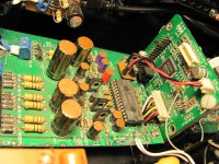
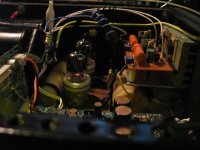
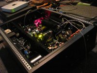
For inspiration, this is Pedja's board with Ians I2S to PCM board..
Finally got it all into a proper box. Nice and quiet.. time to put the lid on.
Mundorf Zn output caps potted in bamboo tubing with Elephant ear wax from the zoo !
Finally got it all into a proper box. Nice and quiet.. time to put the lid on.
Mundorf Zn output caps potted in bamboo tubing with Elephant ear wax from the zoo !
Attachments
Last edited:
Member
Joined 2006
Thank you CFT for all your work.
I saw the nice picture in the GB, I'm asking myself if a nice NDK crystal can let the AYA2 to a more better step ! Saw also the smart position of the CS chip for spidf near the TDA chip below for minimum jitter !
Ceglar, nice DIY ; I begann to try to understand Acko USB work or HIFIDUINO one as Pedja Rodjic will provide also uf.l links.
For people who want a nice chip, Mr Rodjic is known to provide with his Kits (provided here in the populated kit) and devices the best genuiine TDA chip avialable from 2000 years which are said to be equal to a S1 grad;
For the others : well this thread was for enthusiasts of TDA1541 assuming they have already at least one of this chip. But I assume than some owners involved by others projects will sell one of their TDA1541.
Take care to fakes also. Best is to buy an ancient Device (look at Vasily list) for few bucks but some fellows are of course serious.
Well, 35 euros, maybe less for the SOTA PCB with Power supplice embeded is a great gift from Audial. With all the components 400 euros for the Kits with all the parts populated is an another gift for the less skilled of us but still lover of good music.
I'm happy to see than the naives & positivists people from the beginning has arrived with sens of humour and good willing without prejudices to share all togethers with both a famous Brand and fellows to let this project born ! We will have several PCBs : Audial, RyanJ, hope more with others involved fellows and a Kit of a SOTA quality like not most of EBAY kits.
Thank you to all to bring in this thread what you had for sharing.
I saw the nice picture in the GB, I'm asking myself if a nice NDK crystal can let the AYA2 to a more better step ! Saw also the smart position of the CS chip for spidf near the TDA chip below for minimum jitter !
Ceglar, nice DIY
; I begann to try to understand Acko USB work or HIFIDUINO one as Pedja Rodjic will provide also uf.l links.For people who want a nice chip, Mr Rodjic is known to provide with his Kits (provided here in the populated kit) and devices the best genuiine TDA chip avialable from 2000 years which are said to be equal to a S1 grad;
For the others : well this thread was for enthusiasts of TDA1541 assuming they have already at least one of this chip. But I assume than some owners involved by others projects will sell one of their TDA1541.
Take care to fakes also. Best is to buy an ancient Device (look at Vasily list) for few bucks but some fellows are of course serious.
Well, 35 euros, maybe less for the SOTA PCB with Power supplice embeded is a great gift from Audial. With all the components 400 euros for the Kits with all the parts populated is an another gift for the less skilled of us but still lover of good music.
I'm happy to see than the naives & positivists people from the beginning has arrived with sens of humour and good willing without prejudices to share all togethers with both a famous Brand and fellows to let this project born ! We will have several PCBs : Audial, RyanJ, hope more with others involved fellows and a Kit of a SOTA quality like not most of EBAY kits.
Thank you to all to bring in this thread what you had for sharing.
Last edited:
For inspiration, this is Pedja's board with Ians I2S to PCM board..
Finally got it all into a proper box. Nice and quiet.. time to put the lid on.
Mundorf Zn output caps potted in bamboo tubing with Elephant ear wax from the zoo !
Very nice work indeed.
Shane,
I know the little bear brother of the Elephant, he is working on a doc about the "The TDA return" in the spirit of the Midle-Age :
Pub canal plus avec l'ours 2013 - YouTube
He gave all its guts to this project...
I know the little bear brother of the Elephant, he is working on a doc about the "The TDA return" in the spirit of the Midle-Age :
Pub canal plus avec l'ours 2013 - YouTube
He gave all its guts to this project...
Shane,
I know the little bear brother of the Elephant, he is working on a doc about the "The TDA return" in the spirit of the Midle-Age :
Pub canal plus avec l'ours 2013 - YouTube
He gave all its guts to this project...
Hi Eldam,
Ha!.. you know I would have settled for wookie ear wax.. but at the parlour every time I mentioned wax, they were expecting hair/fur removal. The woks were mostly the same, so elephants it was. I mean, you can't wax an elephant, well.. maybe you can but I haven't had any come into the store (yeah, ok so the doors aren't big enough but its not like they're waiting around outside, either).. and so of to the Forest Moon Zoo it was.
On a more serious note, its really nice to see that you've managed to turn this kind of aimless thread (with the help of CFT, ryanj, Audial.. and others) into a place now where there are two options for 'better than good enough 1541A' projects available.
You've done it!. Well done.
All the best.
Shane
Last edited:
Member
Joined 2006
Thanks guys I appreciate. It's few things as I'm not Mother Théresa  ,
, I just share a little of my time (like Alexiis and Audiolapdance e.g. also) to try to drive in a funny way as it was the only thing I had because a lack of technical background. Most of people gave here a little of their time AND knowledge and I surmise it's not finished yet.
This is a collective good-willed sharing factory.
RyanJ drawned, people gave him inputs to increase the result with just the hope to have maybe something one day without insurance. Many gave without personal interest as they don't want a TDA1541 DAC and just help in the spirit of DIYAUDIO... Or V.I.P.s like Pedja, John, Thorsten... whom gave a gift with their great knowledge and hints to allow more DIY experiences.
And the icing of the cake is the material contribution of Audial brand with Pedja Rodjic a special AYA2 2014 revision with some inputs given by DIY comunauty & from John (ECdesigns) also & for a charity curse only. A little of this will be given to a local Jazz festival in Serbia... yes for real live music
.Two great but little brands (in relation to some giants brands) can forgett the economic competition and share for such operation ! It's really great !
Share what you have to give for a project together with nice & fun time: you will have maybe more than having fear alone to be stolen. It's harder to give to others than to keep for oneself but most of the great challenges come from sharing something. A "good enough" world is better than nothing and it's really funnier together

I will open a build thread for the AYA 2014 kit to try to win time together for helping as Pedja already give a lot to us.
This thread is going on with DIY coreboards and ideas for input & output daughter boards.
i think RyanJ after a test boards made with its printer will need some good inputs about good suppliers to print the "good enough" coreboard with a good quality.
Thank you all for sharing
How bout a Thorsten tube output stage and power supply, maybe with transformers like his addagio?
Hi Luke,
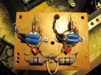
If you search around you'll find that his most recent circuits use resistor I/V and the DC output from 1541A (-2mA) current to bias the tube (in combination with some cathode resistance, but not much).
This is all easily built point to point with a couple (or one) sockets
D3a might look like this (or not), but its very straight forward, and with lower Gm tubes, even moreso.
T's B supply might differ, but theres no hard and fast rule.. same with heaters (DC). The main T idea is low bias and utilising the offset current from the 1541A.
No idea how it compares with his cd77 and dp777 implementations but from what little I know, this is a simpler approach (better? dunno) but it was suggested as 'what he would do' not so very long ago. http://www.audioasylum.com/cgi/vt.mpl?f=tubediy&m=221747&VT=T
If you need some ideas, I have a scheme for 5V4G - 2uF - 10H - 110uF then split to [10H - 55uF] per channel, with adjustable CC sourced heater supply which floats at 35V. Heavy 10mA shunt R's across each final filter per channel to help lower noise.
hth
--
Ryan, Eldam, Cheung, others… I'd like to see a daughter board for DEM cct with a divider chip from BCK with selectable (jump) division for ryanj board.. maybe something to think about..
Regards,
Shane
Attachments
Last edited:
Hi Shane,
Im keen to try another tube output stage but what about exceeding the output compliance of +-25mV on the 1541? With the circuit you posted wouldn't this figure be around +-78mV? Or doesn't this seem to matter?
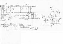
Have you tried Cen/Sen? I highly recommend it. Ill post schematics of my setup. (I may have already posted it)
In the schematic you could omit the NTC, R8, C3. And Add a cap parallel with R3.
The 18V floating supply is 5, 3.7V lithium cells which give about 20 hours of listening depending on the Idss of the jfets (recommended 15mA+)

Im keen to try another tube output stage but what about exceeding the output compliance of +-25mV on the 1541? With the circuit you posted wouldn't this figure be around +-78mV? Or doesn't this seem to matter?
Have you tried Cen/Sen? I highly recommend it. Ill post schematics of my setup. (I may have already posted it)
In the schematic you could omit the NTC, R8, C3. And Add a cap parallel with R3.
The 18V floating supply is 5, 3.7V lithium cells which give about 20 hours of listening depending on the Idss of the jfets (recommended 15mA+)
Last edited:
- Status
- This old topic is closed. If you want to reopen this topic, contact a moderator using the "Report Post" button.
- Home
- Source & Line
- Digital Line Level
- Any good TDA1541A DAC kit?