With 100k input impedance, you really don't need to worry so much.. the rule of thumb is 1:10, so even 10k might be acceptable and 2k from 5687 is certainly no problem. If your amp has high enough input sensitivity then mu 20 from 5687 and an appropriate I/V resistor is probably enough, too.
I saw this 5687 tube was loved in many line stage for preamps ! And also its european equivalent at Philips but said to be far less musical than a <1960 Tungsol or Rayethon... and thick tubes maid for intercontinental nuclear rocket (surmise this last to be able to make music if falling on my roof!....
 microsonics for tubes !)
Hi andrea, is the queen a 300b?
No, it's not the 300B, nor the 845, neither the 211....
Be patient, some months (build & test) and you will know the tube type.
Shane, since you are familiar with the D3a, maybe you have more free time than me, would you test the modified Broskie with a pair of D3a?
Let me know.. if yes I'll publish a simulation where the impedance seen from the TDA is around 1 ohm, that could be a starting point to build a prototype.
Have you ever used the D3a with low HT (60-80 V)?
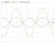
The model I used to simulate the circuit seems to perform very well in that condition (the grid of the first tube swings from -100 mV to +100 mV, cathode set to 0V, TDA output swings from -2 mV to +2 mmV)
No, it's not the 300B, nor the 845, neither the 211....
Be patient, some months (build & test) and you will know the tube type.
Shane, since you are familiar with the D3a, maybe you have more free time than me, would you test the modified Broskie with a pair of D3a?
Let me know.. if yes I'll publish a simulation where the impedance seen from the TDA is around 1 ohm, that could be a starting point to build a prototype.
Have you ever used the D3a with low HT (60-80 V)?
The model I used to simulate the circuit seems to perform very well in that condition (the grid of the first tube swings from -100 mV to +100 mV, cathode set to 0V, TDA output swings from -2 mV to +2 mmV)
Hi Andrea,
I have D3A at about -0.5Vg and 10mA which has plate at approx 65V with the horizontal load line. The CCS needs ~50V to operate so HT can vary from 120V right up to the limits of dissipation without any meaningful change to operation.
The Broskie cct is interesting to me, but my heater supply isn't rated for 1.3A and I'm trying to work on having 'less time', this stuff doesn't pay the bills, as you know.
The queen with mu 300 and low Rp.. something like a triode connected high Gm pentode with g1 and g2 tied together..??
Regards,
Shane
The queen is not a pentode, it's an indirect heating triode.
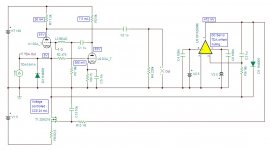
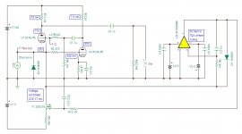
About the modified Broskie with the D3A, if someone had the time to experiment, this is a starting point (with a simple capacitor multiplier as the HT).
Attachments
NFB to the grid of the first stage.. it sure is interesting..
Andrea, I'm wondering the effects on linearity with such a light plate load on the first section, is low impedance plate load necessary to the operation of the circuit or could it use 1k2 in series with plate choke?.
Regards,
Shane
Andrea, I'm wondering the effects on linearity with such a light plate load on the first section, is low impedance plate load necessary to the operation of the circuit or could it use 1k2 in series with plate choke?.
Regards,
Shane
Andrea,
re: Broskie I-to-V
If anyone can shed some light, Broskie discusses the gain of the stage as a ratio, which is understandable as output voltage is defined, but there is no input voltage strictly speaking as its a current and the tube is the converter.
His illustration is 1mA peak signal for 1v peak output.. suggests its ratio as 9, so for every mA you get 1 volt, a very handy 18v peak from 2mA peak signal from 1541A. .. but what tube is he using?, or is this irrespective of tube type (how so?).
With such huge amounts of voltage gain, it seems practical to use a twin triode that has reasonably high Gm, like 6922 or 5687. I'm not sure that I see advantage of using single section tubes like D3A etc, Rp is the same as 5687.
Any thoughts?.
Shane,
keep in mind this circuit is a little different from the original Broskie's, that uses a classic DC servo and V1 is set with negative grid.
In this case there is a voltage controlled CCS to set the bias point of V1 and to null the offset at the output of the DAC (DC servo).
So the grid of the first tube is set to 0V, and swings from -100 mV to +100 mV when the signal is applied (the grid goes positive).
NFB is the basic of the Broskie I to V, but I'm not much worry about that, because there is almost no phase shift in the feedback loop.
As I said, I have no time at now to experiment, so I simulated the circuit:
- input and output signals are in the plot I posted
- simulated THD is less than 0.01%
One can use almost any kind of triode, with this simple rule:
the higher the gain of the tube, the lower the input impedance,
with obvious benefits for the DAC
Keep in mind the grid of V1 will go positive, so the chosen tube has to be linear in this region (the Queen is a good choice)
Thanks Andrea,
It seems that its Rp/mu squared which determines the input impedance, as you say.
5687 1800/324 = 5.55 ohm
6922 3000/1089 = 2.75 ohm
D3A 2000/5625 = 0.35 ohm
If voltage gain is determined by the value of load resistance to an upper limit which is equal to mu squared, that is quite incredible.
With a plate load CCS and output from 'mu' node, it seems possible for super low input and output impedances and massive amounts of voltage gain.
I'd like to find a way to keep the grid of V1 slightly negative at all times.
6922 might be worth the breadboard, two tubes for stereo ~700mA heater current, 2.75 Zin, 200 ohm Zout, voltage gain out the whazoo !!
Shane
His illustration is 1mA peak signal for 1v peak output.. suggests its ratio as 9, so for every mA you get 1 volt, a very handy 18v peak from 2mA peak signal from 1541A. .. but what tube is he using?, or is this irrespective of tube type (how so?).
With such huge amounts of voltage gain, it seems practical to use a twin triode that has reasonably high Gm, like 6922 or 5687. I'm not sure that I see advantage of using single section tubes like D3A etc, Rp is the same as 5687.
Any thoughts?.
If we only have +/-2mA output current wouldn't that only be 4v if 1mA in is 1V out?
Where have I missed the factor of 9?
Chuz,
Drew.
ah, typo.. for every 1mA you get 9v output.
So for 4mA p-p you get 36 vp-p, or 18V peak.
I was stuck on the mA to volt thing and how he calls it '9' and not 9,000. Then realised the voltage out is dependant on load resistor, and his 10k load is where the three extra zeros come from..
So for 4mA p-p you get 36 vp-p, or 18V peak.
I was stuck on the mA to volt thing and how he calls it '9' and not 9,000. Then realised the voltage out is dependant on load resistor, and his 10k load is where the three extra zeros come from..
"So there is no current gain. What he is calling conversion ratio is how much signal voltage in the plate circuit is caused by a given amount of current at the input and he calls 1mA making 9 volts peak of signal a conversion ratio of 9 for some reason not given.
I think I insist on looking at it as voltage gain absent an understandable and compelling reason not to.
Highest gain is (mu + 1) x mu, or mu² + mu.
If you ignore the signal at the cathode of the input tube, the output of the second tube would be (up to) mu times the input voltage signal. That signal goes to the input tube grid. That signal is multiplied again by the mu of the input tube or mu². But there is also a signal of 1 at the input tube cathode. So the signal at the grid WRT the signal at the cathode of the input tube of Mu+1.
The gain seems large, but it is the product of two stages of gain and is slightly more than two conventional stages of gain because of the input signal being connected to the cathode of the first stage where in two conventional stages, the input signal would only be connected to the first stage grid.
And there is no current gain. OK…"
JG in quotation
Shane
Last edited:
Keep in mind the grid of V1 will go positive, so the chosen tube has to be linear in this region (the Queen is a good choice)
I would say linearity is not an issue at this tiny swing. Almost any tube is linear enough for that. The issue is more low enough self noice and that it doesnt start to draw grid current in those regions.
Andrea, could you explain to a layman the I/V process in your schema? Current variations turns to voltage variations over the voltage controlled CSS?
Sometimes the current flowing through the grid cause nonlinearity, that's the reason there are some tubes designed specifically to do the job keeping the linearity when the grid go positive.
You can find a good explanation about the I to V circuit in the Broskie's article.
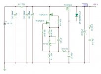
The only difference in the schematic I posted is that I use different DC servo, an operational amplifier drives a voltage controlled CCS, to set the DAC output at 0V.
The DAC loves to see 0V at its output (keep in mind the 1541A swings current from 0 to -4 mA), so we need to null the current flowing through the anodic circuit subtracting 2 mA (half the current swing of the DAC).
In the last schematic I posted, the bias current of V1 is around 19 mA, so to do this job we can use a CCS that provides 17 mA (19-2 mA).
The operational amplifier compares the voltage at the DAC output with the reference (0V), and drives the CCS causing a proportional current variation to keep the TDA output anchored to 0V. When the tubes are cold the bias current is low, so the DC servo reduces the current provided from the CCS.
The two diodes (D1 and D2) prevents high variations to avoid overvoltage at the DAC output.
Let us be positivist : let us choose a tubes design in some month and let us do a grup buy for output transformers at Lundhal to have tubes advantages without the bad outputs caps !
I'm not sure the output caps are so bad, not even they are worse than a transformer.
I'm pretty sure AMR and Zanden use the cap coupling.
We could think to an OTL circuit, but I believe it's a bit more complex.
Reading through the above it seems that there is still a lot of gain, just perhaps not derived through a current gain of 9 as per the article and of course the super low input impedance is also the attraction.
Anything to suggest V1 needs to be the same as V2?. Two triode connected 6688 for L/R V1 and something like (internally shielded sections) 6922 for L/R V2 would have input impedance about 0.55 ohm, linear and tube cost as little as $10 for the two 6688's.
Shane
Anything to suggest V1 needs to be the same as V2?. Two triode connected 6688 for L/R V1 and something like (internally shielded sections) 6922 for L/R V2 would have input impedance about 0.55 ohm, linear and tube cost as little as $10 for the two 6688's.
Shane
Last edited:
Let us be positivist : let us choose a tubes design in some month and let us do a grup buy for output transformers at Lundhal to have tubes advantages without the bad outputs caps !
Well, if stage gain is roughly mu squared you could certainly use a step down transformer. Say LL1660 as 4.5:1., it has enough primary inductance for Rp 2k types.
Best bang for buck might be 6688, where else to get a SQ 10,000hr tube thats linear, high Gm, low Rp, high gain for $5?
For arguments stake assume mu 50, and Rp 2k, so input impedance is less than 1ohm, I'm still stuck on this stage gain thing.. can it really be 2500?..
Anyway, assuming gain is sufficient for 4.5 step-down, output impedance would be 100 ohms.. and not increasing as frequency decreases as is the case with Xc from a capacitor.
Theres seems to be a lot to like about it..
I'm a bit 'at sea' with this very high gain, low input impedance focus to get a 2Vrms output, now complicated with an output transformer?
With 4 x 6C45s, separate +100 & -15V supplies, floating 2 Amp heaters, servo supplies, and so on, this things is rapidly becoming a 'serious project', even without a Broskie output buffer, if used - it would simplify things a lot if twin triodes could be used, but not sure about sound quality....
What's a pair of LL1660, or something similar, cost these days?
All very intriguing - reminds me a bit of Nelson's D1 fet, or Spencer's jfet o/p stage, but done 'in glass'
- Status
- This old topic is closed. If you want to reopen this topic, contact a moderator using the "Report Post" button.
- Home
- Source & Line
- Digital Line Level
- Any good TDA1541A DAC kit?