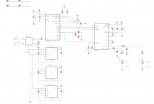
Coax SPDIF, through DA101C isolation transformer, WM8804 SPDIF receiver, I2S to WM8524 DAC, pot to adjust the volume.
24 bit I2S, receiver configured in hardware mode.
WM8524 puts out 2 Vrms, hence the 50K resistor in series with the output from the DAC. Using a 50K pot, that gives me about 1 Vrms, which is the maximum input level that my almost finished headamp will take before clipping. Otherwise, I wont be using the pot to its fullest, reaching maximum output of my headamp already at 12 O'clock without the 50K resistor in series with the DAC output.
Any serious mistakes I need to look into before I go on with making the PCB's?
Attachments
Last edited:
Hi, the schematic looks OK but I will check again later. Some of my experiences which probably will be shot on sight by other members:
- put the regs reasonably close and the decoupling caps as close as possible to the supply pins of the chips.
- Add pads for using high quality 22 uF - 47 uF electrolytic caps with 2.5 mm pitch close to the chips instead of ( so not with) the SMD decoupling caps. Nice for experimenting ! Try to source Black Gate NX HiQ caps for this purpose.
- use beads after the regs to the chips
- Use a different DAC like ES9023 with low jitter XO")
- add a resistor at the primary side of 120 Ohm and use 200 Ohm at the secondary side of the SPDIF transformer
- Use ADP150/151 regs or better. Same footprint. Certainly not LP2950 or LM1117 !
- Add a fourth 3.3 V reg so every chip can have separately 3.3 V digital and 3.3 V analog supply.
- Most transformers have 2 windings, you can use the extra winding to feed the 3.3 V reg of the WM8804's PLL and the analog side of WM8524 separately. This will need an extra bridge and filter cap + extra 7805.
- Add bridge rectifiers and filter caps on the same PCB to avoid extra wiring. Add Phoenix connectors for a 2 x 7 V to 2 x 9 V transformer.
- So make it a complete DAC PCB with the power supply on the same PCB. Modular design is old fashioned by now.
- Make an analog branch and a digital branch if you have 2 windings on the transformer
- Add a prereg in both branches in the form of a 7805 per branch to drop the input voltage to the SMD 3.3 V regs to 5 V.
- Use MKT, MKP, Styrol or even better film caps at the output for filtering. No SMD ceramic caps at that spot.
- Use a Wima MKS2 1 uF film cap with 2.5 mm pitch for the charge pump at WM8524 (C10). Cap close to the chip and short PCB tracks to it please. See the datasheet for optimal layout and put pads for through hole Wima cap on top of the SMD pads for the 1 uF. Then you can try both SMD and TH caps.
- Omit the 50 k resistors at the output. I understand your reasoning but it will not perform as it should.
- Make an extra PCB for me
- put the regs reasonably close and the decoupling caps as close as possible to the supply pins of the chips.
- Add pads for using high quality 22 uF - 47 uF electrolytic caps with 2.5 mm pitch close to the chips instead of ( so not with) the SMD decoupling caps. Nice for experimenting ! Try to source Black Gate NX HiQ caps for this purpose.
- use beads after the regs to the chips
- Use a different DAC like ES9023 with low jitter XO
- add a resistor at the primary side of 120 Ohm and use 200 Ohm at the secondary side of the SPDIF transformer
- Use ADP150/151 regs or better. Same footprint. Certainly not LP2950 or LM1117 !
- Add a fourth 3.3 V reg so every chip can have separately 3.3 V digital and 3.3 V analog supply.
- Most transformers have 2 windings, you can use the extra winding to feed the 3.3 V reg of the WM8804's PLL and the analog side of WM8524 separately. This will need an extra bridge and filter cap + extra 7805.
- Add bridge rectifiers and filter caps on the same PCB to avoid extra wiring. Add Phoenix connectors for a 2 x 7 V to 2 x 9 V transformer.
- So make it a complete DAC PCB with the power supply on the same PCB. Modular design is old fashioned by now.
- Make an analog branch and a digital branch if you have 2 windings on the transformer
- Add a prereg in both branches in the form of a 7805 per branch to drop the input voltage to the SMD 3.3 V regs to 5 V.
- Use MKT, MKP, Styrol or even better film caps at the output for filtering. No SMD ceramic caps at that spot.
- Use a Wima MKS2 1 uF film cap with 2.5 mm pitch for the charge pump at WM8524 (C10). Cap close to the chip and short PCB tracks to it please. See the datasheet for optimal layout and put pads for through hole Wima cap on top of the SMD pads for the 1 uF. Then you can try both SMD and TH caps.
- Omit the 50 k resistors at the output. I understand your reasoning but it will not perform as it should.
- Make an extra PCB for me
Last edited:
I forgot some:
- Use 22 Ohm resistors in the data lines to the DAC chip.
- You can add pads for a low jitter 5 x 7 mm XO for MCLK with its own 3.3 V reg....
- A Lock LED would be nice
- Triple check grounding scheme
- Compare your schematics with this one:
http://www.wolfsonmicro.com/documents/uploads/misc/en/WM8524_6228_DT16_EV1_SchematicLayout.pdf
Last edited:
After light checking of the schematics I think you configured WM8524 in RJ not I2S. AFAIK pin 12 should be 1 not Z. To busy right now but please check this.
Pin 12 on WM8524 is 1, see the 10K pull-up to VDD.
Well, I could use an ES9023 DAC but the WM8524 is what I chose and I'm sticking with it. Maybe on some future V2 of my board I might try the ES9023 or something even better.
Im using TPS76133DVBT regulators, not the best there is but for my requirements it will work very well. This Input board will be mounted inside my head amp. My headamp will run on +15/-15 V regulated suppllies so the Input board regulators are fed with a +15V well regulated supply.
Regarding adding a fourth regulator, that is certainly possbible, did consider that myself.
You resistor choice for the primary and secondary sides of the SPDIF isolation transformer seems weird. Firstly, you shouldnt really need a resistor on the primary side in the first place and on the secondary side you usually terminate with 75 Ohm and not 200 Ohm. What is the reason for your resistor suggestions?
Also, why wouldnt the 50K resistor at the output work?
You could try using another Wolfson DAC that has digital volume control (WM8523), which will give much better results.
The way you have the pot wired above, you will have a huge and widely varying output impedance.
You are correct, it will have a varying output impedance. Is there any way to get around this when using a pot or atleast minimize it?
I'll look at the WM8523 as well.
Is there any way to get around this when using a pot or atleast minimize it?
Add a buffer after the pot.
The digital volume will require a uC, but it's really worth it.
The resistor series with the pot will just lower the singnal-noise ratio of the DAC. If the next stage has too much gain, reduce it there, don't reduce the input signal...
Plus, at 50k output impedance you are asking for EM interferences on the connecting cables.
A 10K pot would do it.
Well, I could lower the gain of my headamp, no problem there, and then switch to a 10K pot instead, without any series resistance.
But then there would still be a varying output impedance, albeit with a smaller range.
WM8523 looks interesting, but requires more external circuitry for the digital volume control, which I'm not sure that I am willing to implement.
But then there would still be a varying output impedance, albeit with a smaller range.
WM8523 looks interesting, but requires more external circuitry for the digital volume control, which I'm not sure that I am willing to implement.
Last edited:
Pin 12 on WM8524 is 1, see the 10K pull-up to VDD.
I read Z to be a resistance as I would not know otherwise what Z means. A logic 1 is I2S. My mistake ?
Well, I could use an ES9023 DAC but the WM8524 is what I chose and I'm sticking with it. Maybe on some future V2 of my board I might try the ES9023 or something even better.
Im using TPS76133DVBT regulators, not the best there is but for my requirements it will work very well. This Input board will be mounted inside my head amp. My headamp will run on +15/-15 V regulated suppllies so the Input board regulators are fed with a +15V well regulated supply.
Regarding adding a fourth regulator, that is certainly possbible, did consider that myself.
You resistor choice for the primary and secondary sides of the SPDIF isolation transformer seems weird. Firstly, you shouldnt really need a resistor on the primary side in the first place and on the secondary side you usually terminate with 75 Ohm and not 200 Ohm. What is the reason for your resistor suggestions?
Also, why wouldnt the 50K resistor at the output work?
- Never go for better (and cheaper) DAC parts otherwise you will reach your goal of a good sounding DAC too fast
- TPS76133 don't work very well at all as they have a whopping 190 uV noise ( BW from 300 Hz to 50 kHz). This means they're totally unsuitable for this task as they even have more noise than for instance the 78XX series....
- the regs may become too hot as you will feed them +15 V. Do the math with the current the chips will use and calculate dissipating power. You should use preregs to drop the voltage or a dedicated transformer as suggested.
- Don't be surprised if feeding the DAC with the 15 V from the headamp will have its effect on that same 15 V if that is a voltage for analog purposes.
- the resistors present 75 Ohm but you can figure out why. Adding extra pads leave you the possibility for trying out.
- Reasons for not using 50 k in series have been explained well by others.
- try to make it good (as in: the best you ever made) and not mediocre as it will probably cost more than many Ebay DACs to build so it should be better... The difference between mediocre and very good might be just a few Euro.
Last edited:
I read Z to be a resistance as I would not know otherwise what Z means. A logic 1 is I2S. My mistake ?
- Never go for better (and cheaper) DAC parts otherwise you will reach your goal of a good sounding DAC too fast
- TPS76133 don't work very well at all as they have a whopping 190 uV noise ( BW from 300 Hz to 50 kHz). This means they're totally unsuitable for this task as they even have more noise than for instance the 78XX series....
- the regs may become hot as you will feed them +15 V. You should use preregs to drop the voltage or a dedicated transformer as suggested.
- Don't be surprised if feeding the DAC with the 15 V from the preamp will have its effect on that same 15 V.
- the resistors present 75 Ohm but you can figure out why. Adding extra pads leave you the possibility for trying out.
- Reasons for not using 50 k in series have been explained well by others.
Pin 12 can be tri-stated, that is 0, 1, and Z, with 0 being connetion to GND, 1 being pull-up to VDD and lastly Z being unconnected.
Hmm, I havent looked into the nosie figure of TPS76133, however, I might find a better regulator and then use a pre-regulator to drop the voltage.
EDIT : Also, one of the reasons for not using ES9023 is availability, buying from the distributor here in Scandinavia cost alot in shipping(£80) so it is not readily available even though the price for the DAC itself is very reasonable.
Last edited:
So hows this, OPA2134 OP-Amp as output buffer, with a 10K pot after it and reduced gain in the headamp stage to make it work with 2Vrms.
An extra opamp is, well, an extra opamp. Extra (in the sense of more than required) stuff doesn't make things better usually. Keep it simple by applying a volume potentiometer where is should be (not at the DAC side).
Last edited:
- Status
- This old topic is closed. If you want to reopen this topic, contact a moderator using the "Report Post" button.
- Home
- Source & Line
- Digital Line Level
- Schematic review, Coax SPDIF receiver-DAC-Volume pot