That is your personal truth but not necessarily a universal one.
The circuit physics are not my personal truth. They are simply, the truth. You continue to confuse, intentionally or not, your own personal preferences for the engineering physics involved. My objection with your plans has never had anything, whatsoever, to do with what are your own preferences or listening objectives. We all have those. No, my objection has to do with your disregard or dismissal of established circuit functioning. As I wrote earlier, you are entitled to your own listening preferences, but you are not entittled to you own circuit physics.
With that said, I think we've wasted enough time and effort on each other. I'm quite certain I have. Adieu.
Last edited:
I guess a virtual ground is good enough...
Actually, no ground connection is required at all for the DAC chip Iout pins.
you are talking about 9018 here right? it very much DOES need a low impedance return to get good performance. if you arent talking sabre, my appologies
I've never talked about this sabre DAC, sorry for the confusion. I don't know anything about that particular one. I'm referring to the PCM1794 with balanced current output, that is all.
no dramas, the confusion is probably all mine, sorry for that =)
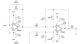
Thanks for your interest. I've been trying to reconcile two apparently conflicting bits of information; one that said that current output DAC's prefer to see zero (or near zero) ohms to ground on their Iout pins and another that showed a transformer primary connected across the + and - Iout pins with no connection to ground. There are several commercial implementations of both but I think I've resolved it now.
- Status
- This old topic is closed. If you want to reopen this topic, contact a moderator using the "Report Post" button.
- Home
- Source & Line
- Digital Line Level
- DAC project