abraxalito any chance the designer speaks english and you have his email? I can't get the schematics, and I'm curious what has been implemented in the circuit.
re: Grounding, I've attached a picture of the completed dac. I use separate mains transformers for each PS. How could I improove grounding?
re: Grounding, I've attached a picture of the completed dac. I use separate mains transformers for each PS. How could I improove grounding?
Attachments
Last edited:
Hi,
Yes, it will. The inputs on the 8805 expects SPDIF levels, you need to switch it (in software) to CMOS levels if you want to feed these.
Further, looking at your DAC, I am unsurprised that there is no appreciable improvement, given the design as it is.
One of the main "on board" jitter generators (the digital filter) is not addressed by re-clocking and many of circuit choices are extremely dubious, including the apparent lack of any competent HF decoupling for digital circuitry. To me this DAC appears like a ruddy waste of a rather decent chipset.
Ciao T
Could you expand on these improvements, or should I start a new thread on that subject? I'm quite suprised at how good the dac sounds, actually, but another level of improvement would be great!
Hi,
Sorry, I really do not have the time to fix every ones else's bad design, especially bad PRC Design. Maybe abraxalito would like to help out.
If you like the way the DAC sounds, why not just enjoy the music and stop messing with it.
Ciao T
Could you expand on these improvements, or should I start a new thread on that subject? I'm quite suprised at how good the dac sounds, actually, but another level of improvement would be great!
Sorry, I really do not have the time to fix every ones else's bad design, especially bad PRC Design. Maybe abraxalito would like to help out.
If you like the way the DAC sounds, why not just enjoy the music and stop messing with it.
Ciao T
I did not say that it does work well. You just cut that part of my reply.As Cirrus logic found out in their CS8416 when it had around 10 times of the jitter of the earlier parts, it does not work as you might think it does.
I really don't care if 8805 it is "working", I wasn't at all my point.Well, whatever is in there does appear to work in practice like what they claim (according to AP Sys 2722).
I care that they deceive purposely about the function of that crystal (on the marketing part of their datasheet) and probably about the FIFO buffering. And that false information gets spread on forums...
Then people ask legitimate questions like the one that started that thread "why is not sounding better"?
Last edited:
I did not say that it does work well. You just cut that part of my reply.
I really don't care if 8805 it is "working", I wasn't at all my point.
I care that they deceive purposely about the function of that crystal (on the marketing part of their datasheet) and probably about the FIFO buffering. And that false information gets spread on forums...
Then people ask legitimate questions like the one that started that thread "why is not sounding better"?
Hi, I don't like the way you want to achieve success. If you like me to agree with you then I will agree with you.
However, you are linking 2 different things together. "Why is it not sounding better" is about a design that obviously is not working good/as it should. It is not depending on the used WM8805. That chip is by now a known good component so one tends to assume that an adapter PCB to replace CS8414 would perform better. However the way the chip is applied on this adapter PCB is of importance, the way the designer implemented it is not OK and some functions even don't work at all.
It has nothing to do with "false information that get spread on forums". Call it whatever you want to call it (dejittering, a good PLL, a good chip) but WM8805 and WM8804 are simply ahead of CS8416 and DIR9001 and being a simple person I tried them in hardware mode and found out that they are good. I never tried AKM parts so I don't have an opinion on those.
I think Thorsten pointed out that WM8805 does achieve what Wolfson claims so stating that they are lying is quite bold. Wolfson has a good reputation and deceiving and lying are strong words. You are not working for Cirrus are you ?
")
Last edited:
[any chance the designer speaks english and you have his email?
I met him earlier this year (I went with a cute interpreter) - he speaks not a word of English and I don't have his email. I could attempt to get a message to him if you want to ask him something - I have an associate who chats to him on QQ from time to time. PM me if that's any use.
I can't get the schematics, and I'm curious what has been implemented in the circuit.
He sent me the schematic for the DAC I linked to along with the DAC itself. He's very sensitive about having his designs copied, that might be one reason he doesn't give out schematics.
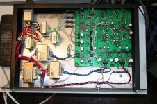
re: Grounding, I've attached a picture of the completed dac. I use separate mains transformers for each PS. How could I improove grounding?
The separate meains trafos are potentially a good thing, especially because they're EI types, hence low capacitance to mains. Unfortunately the board in your picture is beyond practical remedy because its using what looks like a single groundfill for ground. Unless you enjoy spending many thankless hours with a craft knife 'hacking up the turf' so to speak, I'd choose a different starting point if your aim is good sound.
There is nothing wrong with a ground fill by itself.
Bad is when you have digital power rails mixed with the analog one, when you have ground loops - like I see with the unshielded bifilar signal conductors. Is bad also the fused ground (like the one on 12-12V transformers for analog). Also, rotate the analog transformers with 90 degrees in relation with digital ones.
I personally think that is overkill. You have too many transformers, they don't help at all. What's the reason to have one for each OpAmp I/V filtering stage and one for DAC's? One transformer can handle all those miliampers with ease and no interference. Maybe use bigger filtering capacitors instead... And I like to see more decoupling capacitors close to DAC and OpAmp (the ones close on rectifyers don't count) - are they on the back? You need one between each rail and ground. Same on digital side - decoupling is too far "out" from chips.
Last edited:
There is nothing wrong with a ground fill by itself.
Well of course I agree, a groundfill by itself has no sound.
Agree with ThorstenL.
CS8414 is not the weakest link in this DAC. Even input buffer alone is contributing much more jitter than receiver chip.
Are you telling us that Chinese designers are affraid that another Chinese designers will copy their POC designs? This must be joke, who in their right mind would do that?
CS8414 is not the weakest link in this DAC. Even input buffer alone is contributing much more jitter than receiver chip.
He sent me the schematic for the DAC I linked to along with the DAC itself. He's very sensitive about having his designs copied, that might be one reason he doesn't give out schematics.
Are you telling us that Chinese designers are affraid that another Chinese designers will copy their POC designs? This must be joke, who in their right mind would do that?
Are you telling us that Chinese designers are affraid that another Chinese designers will copy their POC designs? This must be joke, who in their right mind would do that?
I appreciated the irony too. No I'm telling you that I know of one Chinese designer who is afraid of other Chinese designers copying his designs. His designs certainly aren't state of the art, but they're so cheap I don't much care and they do serve as great modding platforms. His fear is such that he sells almost totally on eBay and avoids the local taobao (where Chinese are much more likely to buy and copy).
I thought that being copied was an honor in China? That proves that you do a good job?
Ah, honor doesn't pay the bills? They finally figured that one out...
PS: I like some of the chinese (taiwan) DAC's on eBay. Tempted to buy one just to see how they are really build. Some of them I bet are posting on this site, I can spot them from the NOS virus that pops in some of their products
Ah, honor doesn't pay the bills? They finally figured that one out...
PS: I like some of the chinese (taiwan) DAC's on eBay. Tempted to buy one just to see how they are really build. Some of them I bet are posting on this site, I can spot them from the NOS virus that pops in some of their products
Last edited:
I thought that being copied was an honor in China? That proves that you do a good job?
Indeed it is, its a way of 'giving face' in the traditional culture. But I'm guessing that this guy's been infected by Western Capitalist mores, he's only paying attention to potential lost revenue.
Hi,
My point is that when you get it to work the WM880X does work well, so they cannot use this particular method you suggest...
Sorry for mistaking that. I was under the impression that you felt that WM were lying about how the chip worked AND how it performed.
They lie? You mean like Tony Bliar who said Iraq could deploy WMD's in 15 Minutes when in fact Iraq had non that where in any state to be deployed?
Let's see what they say:
I would say that "crystal derived" is a fair description of using a Fractional N DPLL with crystal reference to generate the master clock.
Well, I have not been able to analyse the WM8805 on a silicone level, so I cannot 100% confirm they use a FIFO and the FIFO Fill Level to control the frequency programmed into the Fractional N DPLL clock generator.
However, it seems an eminently workable principle and the WM880X certainly works using this programmable clock (otherwise there would not be the 176.4/192KHz locking issue).
Yes, it does, doesn't it. The only question here is who actually is spreading lies, innit?
Well, "Why does it not sound better?" is a valid question.
My point is that, if a DAC build with CMOS IC's that are operating at clock rates in 10's of MHz range and only uses electrolytic decoupling capacitors placed an inch or more from the IC's they are decoupling in violation of the manufacturers application recommendations for these chips, then the answer to this question may not be to blame the WM8805 based receiver first. In fact, the design flaws in this DAC are so numerous, I find it hard to start to even enumerate them.
And even if the DAC to which said debated receiver module was fitted did not suffer such gross design flaws and the problem was the actual receiver plugin, it would unsafe to automatically assume the WM chip alone was to blame and to ignore the implementation completely.
Ciao T
I did not say that it does work well. You just cut that part of my reply.
My point is that when you get it to work the WM880X does work well, so they cannot use this particular method you suggest...
I really don't care if 8805 it is "working", I wasn't at all my point.
Sorry for mistaking that. I was under the impression that you felt that WM were lying about how the chip worked AND how it performed.
I care that they deceive purposely about the function of that crystal (on the marketing part of their datasheet)
They lie? You mean like Tony Bliar who said Iraq could deploy WMD's in 15 Minutes when in fact Iraq had non that where in any state to be deployed?
Let's see what they say:
Wolfson Micro WM8805 Datasheet said:A crystal derived, or externally provided high quality master clock is used to allow low jitter recovery of S/PDIF supplied master clocks.
I would say that "crystal derived" is a fair description of using a Fractional N DPLL with crystal reference to generate the master clock.
and probably about the FIFO buffering.
Well, I have not been able to analyse the WM8805 on a silicone level, so I cannot 100% confirm they use a FIFO and the FIFO Fill Level to control the frequency programmed into the Fractional N DPLL clock generator.
However, it seems an eminently workable principle and the WM880X certainly works using this programmable clock (otherwise there would not be the 176.4/192KHz locking issue).
And that false information gets spread on forums...
Yes, it does, doesn't it. The only question here is who actually is spreading lies, innit?
Then people ask legitimate questions like the one that started that thread "why is not sounding better"?
Well, "Why does it not sound better?" is a valid question.
My point is that, if a DAC build with CMOS IC's that are operating at clock rates in 10's of MHz range and only uses electrolytic decoupling capacitors placed an inch or more from the IC's they are decoupling in violation of the manufacturers application recommendations for these chips, then the answer to this question may not be to blame the WM8805 based receiver first. In fact, the design flaws in this DAC are so numerous, I find it hard to start to even enumerate them.
And even if the DAC to which said debated receiver module was fitted did not suffer such gross design flaws and the problem was the actual receiver plugin, it would unsafe to automatically assume the WM chip alone was to blame and to ignore the implementation completely.
Ciao T
Thanks for the ground tips and closer decouplig. I found an interresting paper on grounding in mixed signals systems (attached), and seems the chineese followed it pretty well, except getting the decoupling caps closer to the ic's . On the other hand, since each noisy ic has his own power supply, this might be less of an issue, since they don't have much else to inject noise into.
Grounding doc PDF 192K
Grounding doc PDF 192K
Last edited:
Stormsonic,
Are you saying those NAND gates introduce jitter? I'se seen some products like Monachy Audio DIP (highly reviewed) that use a similar technique to raise spdif levels...
Thanks
Agree with ThorstenL.
CS8414 is not the weakest link in this DAC. Even input buffer alone is contributing much more jitter than receiver chip.
Are you saying those NAND gates introduce jitter? I'se seen some products like Monachy Audio DIP (highly reviewed) that use a similar technique to raise spdif levels...
Thanks
Hi,
Sorry, but the circuit has no decoupling cap's at teh frequencies at which it works. Simply stick a 'scope on the supply lines and you will see...
Ciao T
Thanks for the ground tips and closer decouplig. I found an interresting paper on grounding in mixed signals systems (attached), and seems the chineese followed it pretty well, except getting the decoupling caps closer to the ic's.
Sorry, but the circuit has no decoupling cap's at teh frequencies at which it works. Simply stick a 'scope on the supply lines and you will see...
Ciao T
Hi
These are not NAND gates, they are inverters. They are operated as analogue amplifiers in part with insufficient decoupling. The impedances in the input circuit are wrong and hence the input impedance at SPDIF frequencies (where it matters) will be much lower than 75 Ohm.
When using the Cirrus Logic chips the raised level is a good thing in principle, though the actual implementation in the Lite DAC is criminally incompetent, so it is likely to harm more than to help even with a Cirrus Logic receiver which is actually designed for 5V Peak-Peak AES/EBU levels...
HOWEVER, when using a WM8805 which has a different input circuit the result of this circuit is entierly negative. The input expects 0.5V Peak-Peak and yet it is driven with 5V Peak-Peak which actually exceeds the WM8805's rail voltage and hence will make the input protection diodes on the WM8805 conduct and saturate with interesting and wide reaching consequences.
Look, if you want to convince yourself that the DAC's design is actually good regardless of the facts and that even though the design goes against most things common sense, basic electronic knowledge and the Chip Manufacturers data sheets and application notes dictate, be my guest. In this case it may best not to ask questions to which you really do not want to know the answers.
Ciao T
Are you saying those NAND gates introduce jitter?
These are not NAND gates, they are inverters. They are operated as analogue amplifiers in part with insufficient decoupling. The impedances in the input circuit are wrong and hence the input impedance at SPDIF frequencies (where it matters) will be much lower than 75 Ohm.
When using the Cirrus Logic chips the raised level is a good thing in principle, though the actual implementation in the Lite DAC is criminally incompetent, so it is likely to harm more than to help even with a Cirrus Logic receiver which is actually designed for 5V Peak-Peak AES/EBU levels...
HOWEVER, when using a WM8805 which has a different input circuit the result of this circuit is entierly negative. The input expects 0.5V Peak-Peak and yet it is driven with 5V Peak-Peak which actually exceeds the WM8805's rail voltage and hence will make the input protection diodes on the WM8805 conduct and saturate with interesting and wide reaching consequences.
Look, if you want to convince yourself that the DAC's design is actually good regardless of the facts and that even though the design goes against most things common sense, basic electronic knowledge and the Chip Manufacturers data sheets and application notes dictate, be my guest. In this case it may best not to ask questions to which you really do not want to know the answers.
Ciao T
Basic decoupling rules are not followed, that's what I said some posts ago:
And I like to see more decoupling capacitors close to DAC and OpAmp (the ones close on rectifyers don't count) - are they on the back? You need one between each rail and ground. Same on digital side - decoupling is too far "out" from chips.
After having checked the schematic of the DAC to understand the comment of Thorsten I see he is absolutely right. Is removing the 74HC04 an option (for the SPDIF side at least) ? So connecting the WM8805 directly to the input RCA. I don't have much time to check further right now.
- Remove the 74HC04 from the input circuit
- RCA input straight to the pad the 74HC04 pin 8 was connected to. Before the 10 nF cap !
- Remove resistors 150 Ohm, 2 x 220kOHm, 1 x 47kOHm and 2 x 10 nF caps connected to the 74HC04
- check if the adapter PCB also has 10 nF cap at the WM8805 inputs, that would mean 2 x 10 nf in series...
Thorsten can you please check if this is right ?
Last edited:
- Status
- This old topic is closed. If you want to reopen this topic, contact a moderator using the "Report Post" button.
- Home
- Source & Line
- Digital Line Level
- WM8805 upgrade board (cs8414 pins) - dissapointed