Hi KlipschKid
Regarding the allowed frequencies, i believe there is a misunderstanding.
Page 22 Datasheet WM8805:
Table 23 on page 25 shows only some examples. I think it is no problem to use say 22.5792 or 24.576 MHz oscillators.
The only problem is that you have to figure out all the PLL settings....
Table 23 in the datasheet may be misleading, as these are only examples for PLL settings.
Regarding better performance:
The OSC frequency has to be divided for locking to the input stream and also for providing MCLK and CLKOUT.
As MCLK and CLKOUT will be integer numbers of fs, at least one family of fs would not require division by fractional numbers when using an appropriate OSC frequency.
Me too, i cannot find the reference in the datasheet which i had in mind. Maybe it was another document, which stated that synchronous OSC frequencies would be superior. Or maybe it was Thorsten who said this, as he implemented this chip for a commercial project.
Regarding the allowed frequencies, i believe there is a misunderstanding.
Page 22 Datasheet WM8805:
Crystal frequencies between 10 and
14.4MHz or 16.28 and 27MHz can be used in software mode.
Table 23 on page 25 shows only some examples. I think it is no problem to use say 22.5792 or 24.576 MHz oscillators.
The only problem is that you have to figure out all the PLL settings....
Table 23 in the datasheet may be misleading, as these are only examples for PLL settings.
Regarding better performance:
The OSC frequency has to be divided for locking to the input stream and also for providing MCLK and CLKOUT.
As MCLK and CLKOUT will be integer numbers of fs, at least one family of fs would not require division by fractional numbers when using an appropriate OSC frequency.
Me too, i cannot find the reference in the datasheet which i had in mind. Maybe it was another document, which stated that synchronous OSC frequencies would be superior. Or maybe it was Thorsten who said this, as he implemented this chip for a commercial project.
Hi,
Thanks for your help. You are quite right. I dunno where I got the idea 24.576 wasn't possible. Thank you very much for pointing that out.
In the test conditions on page 8 they state fs = 48Khz and mclk = 256fs so they are using 12.288Mhz as mclk, and they have generated this from f1 = 12Mhz, and f2 as 98.304Mhz ?
So R is 8.192 for the above and this allows us to calculate PLL_N and PLL_K. They say PLL_N should be 8 for best operation.
It seems we can choose 24.576 and set the prescale to 1 to get f1 as 12.288Mhz ? With r as 8.192 we would get f2 as just over 100MHz - beyond their specified limit. So R would need to be 8.138 max.
Can we still use PLL_N as 8 with the above ?
Last edited:
Is this possible for a 24.576Mhz xo ?
If we decide R = 8.12
f1 = 12.288 f2 = 99.77856 (within limit)
PLL_N is 8 (optimum), then PLL_K = 2^22 (8.12-8) = 503316 = 7AE14 (hex)
In this case R would actually be 8.1199998856 and f2 =99.7785586937
Have I misunderstood how this works ? Table 27 seems to indicate I might have got this wrong...
If we decide R = 8.12
f1 = 12.288 f2 = 99.77856 (within limit)
PLL_N is 8 (optimum), then PLL_K = 2^22 (8.12-8) = 503316 = 7AE14 (hex)
In this case R would actually be 8.1199998856 and f2 =99.7785586937
Have I misunderstood how this works ? Table 27 seems to indicate I might have got this wrong...
Last edited:
How about this for 22.5792Mhz xo ?
R = 98.304 / 11.2896 (prescale =1 so 22.5792 becomes 11.2896 for f1) = 8.7074829932
PLL_N = 8
PLL_K = 4194304 x 0.7075 = 2D4766 (hex)
FREQ_MODE 01 , allows 512fs, 256fs, 128fs for 48Khz, 96Khz and 192Khz from 24.576Mhz
This would let us use the CCHD-957.
I'm pretty sure this will work, so pls ignore the other ideas above. So shall we go for a 22.5792Mhz clock ? It'll mean a problem with RS / Farnell but will enable the use of the best of very low phase noise xo's.
Last edited:
Hi, yes i think that is OK. Important thing is: PLL user mode or S/PDIF receive mode? I think, in this project it must be receive mode (see page 22), isn't it?
In that case, f2=94.3104MHz would be OK for Mode 1 (192kHz fs) according to datasheet Page 27 below and 28.
For Modes 2/3/4 (32 to 96kHz fs) and Mode 1 (176.4MHz) i think f2=94.3104 MHz is required.
In table 23, none of these f2 frequencies are shown, seems as it is the example for user mode only.
What a mess configuring that part, and especially the 176.4/192 kHz detection in Mode 1.
Hi,
Thanks for the reply and your help.
I'm leaving the 176.4 and 192 modes to Abraxalito ! Way beyond me to get them working.
However, for f2 of 94.3104 and 98.304, they will both have R > 8 if the xo is 22.5792 (8.35374 and 8.7075 respectively) so that is looking like the best xo freq to choose to get the PLL_N at 8 as recommended.
11.2896Mhz is also a candidate but that rules out the cchd-957.
I just got a reply from Sylvie at Mercury. She's going to get back to me next week about a 3.3v 22.5792Mhz xo and the phase noise, prices, etc. She says the best is 25ppm but gotta wait and see about the ps.
Thanks again for your help !
Last edited:
Hopefully, with everyone's help, we can get a really good receiver. It seems people want one... so thanks again. If you see any more mistakes, please let me know... ")
I already bought two CCHD 24.576 and one 22.5792 for other projects. They are excellent ! Even with nothing more than an adp150 reg.
I haven't tried to create a lower noise supply for them yet - to see if I can get better performance. Have you tried ?
I was thinking about using an LM723 (2.5uV noise) with a BUP40 pass transistor, to create a 7.25 supply, and then drop that down to 4V using a potential divider; (18K, 22K). The 4v can be fed into the base of a bc550, with a 100uF cap to ground, to create a filtered 3.3V with nV noise, if the layout etc is good enough. One day...
Thanks again.
Hello KlipschKid[...]
I haven't tried to create a lower noise supply for them yet - to see if I can get better performance. Have you tried ?[...]
No i did not buy one yet.
I think i will breadboard something like this. It is similar to what Demian Martin proposed, but as a shunt with pretty high PSSR because of the cascoded depletion MOS-Fet CCS. TL431 is only there to provide stable DC level.
Of course it could be done even simpler, using LED's as reference. Voltage might not be regulated precisely in that case.
Attachments
Hi,
The mosfets are interesting but the tl431 is a little noisy - 40uV - iirc ? Has the circuit been tested ?
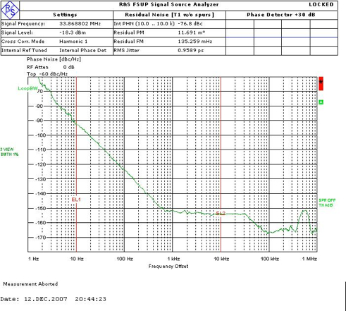
I just received the phase noise plots for the XO91 22.5792. Looks good considering it is an inexpensive xo at RS - US$3. I have used it many times and been impressed so it's good to see the plot to confirm this. I am thinking about ordering some direct from Mercury. Is anyone interested in any ? Or should I just order a few for myself ?
10hz -80dB, 100Hz -108dB, 1Khz -128dB etc with a noise floor of -156dB.
XO91 US$3
CCHD-957 US$30 ~15 to 20dB better
Tent Labs US$40 similar to XO91 but with a lower noise floor
The mosfets are interesting but the tl431 is a little noisy - 40uV - iirc ? Has the circuit been tested ?
I just received the phase noise plots for the XO91 22.5792. Looks good considering it is an inexpensive xo at RS - US$3. I have used it many times and been impressed so it's good to see the plot to confirm this. I am thinking about ordering some direct from Mercury. Is anyone interested in any ? Or should I just order a few for myself ?
10hz -80dB, 100Hz -108dB, 1Khz -128dB etc with a noise floor of -156dB.
XO91 US$3
An externally hosted image should be here but it was not working when we last tested it.
CCHD-957 US$30 ~15 to 20dB better
An externally hosted image should be here but it was not working when we last tested it.
Tent Labs US$40 similar to XO91 but with a lower noise floor
Last edited:
Hi!
Yes, TL431 is noisy. BUT...it's noise is heavily filtered through R1=1k and C2=1000µF, so it should not impress his noise performance on the regulator noise. Around -50dB at 50Hz should be the noise attenuation of TL431 through R1-C2, if I calculated it correctly.
Much more important are the transistors, especially the PNP. AFAIK Joachim Gerhard measured them and found them to be less noisy than BC550/560.
Tino, excuse me, if I'm wrong:
Why do you need LP filter, if you are "pulling" current out from Q1 base?
PNP Transistor (Bipolar)
Why do you need LP filter, if you are "pulling" current out from Q1 base?
PNP Transistor (Bipolar)
Last edited:
Tino, excuse me, if I'm wrong:
Why do you need LP filter, if you are "pulling" current out from Q1 base?
PNP Transistor (Bipolar)
Thanks for the link
Well, AC wise i believe there is still the need to isolate the LT431 from the base. The AC noise is impressed on DC current coming out from Q1, but much smaller than that. But maybe there is not such a huge difference between the schematic i posted and what i thought i had forgot.
I hastly breadboarded this on sunday after my nice went home, but I was not able to measure the noise. Maybe I was already too tired, and red wine during dinner didn't help either....
But I think i need an AD797 at 100x or so to put before my soundcard, to compare to other regulators or simple resistros and enhance the differences.
Hi,
An update on the xo. I can get 50 of the XO91 22.5792Mhz 3.3V <0.5ps jitter 25ppm for US$1 each plus shipping and tt costs. 100 for 80cents each + costs.
I'm wondering if it might be an idea to design a tiny board - dip14 or dip8 size - with adp150, two 2uF smd x7r caps and a ferrite to create a 5v to 3.3V adapter xo ? Even I could do this.
Hi,
I've been listening to the board I got on Taobao and done some changes to see what difference it makes.
As you'd expect, changing the xo makes a noticeable difference.
It came with a 5V 25ppm part I can buy in Shenzhen for a few cents. I tried a Valab 5V tcxo (JYEC part) with phase noise around -125dB @ 1Khz
and that sounded much better. No surprises.
I then added an adp150 3.3V reg and used an xo91 (similar -128dB @ 1Khz) and this improved it again, probably because of the reg and the more suitable output. I really don't think the wm8805 should have a 5V clock ? I seem to remember that it should be no more than 0.3V above the supply, which is 3.3V (page 5 DVDD +0.3V). Is this right ? So why did the seller fit a 5V xo ?
I have fitted the reg so I can swap between 5V dip14 and 3.3V dip8. It seems the lowest phase noise 12Mhz xo is Tent's but I don't have one of those to try.
Next, I'll try changing the regs on the bottom of the board and then the input capacitor.
BTW, I also tested the current draw and the whole thing uses around 90mA.
I've been listening to the board I got on Taobao and done some changes to see what difference it makes.
As you'd expect, changing the xo makes a noticeable difference.
It came with a 5V 25ppm part I can buy in Shenzhen for a few cents. I tried a Valab 5V tcxo (JYEC part) with phase noise around -125dB @ 1Khz
An externally hosted image should be here but it was not working when we last tested it.
and that sounded much better. No surprises.
I then added an adp150 3.3V reg and used an xo91 (similar -128dB @ 1Khz) and this improved it again, probably because of the reg and the more suitable output. I really don't think the wm8805 should have a 5V clock ? I seem to remember that it should be no more than 0.3V above the supply, which is 3.3V (page 5 DVDD +0.3V). Is this right ? So why did the seller fit a 5V xo ?
An externally hosted image should be here but it was not working when we last tested it.
I have fitted the reg so I can swap between 5V dip14 and 3.3V dip8. It seems the lowest phase noise 12Mhz xo is Tent's but I don't have one of those to try.
Next, I'll try changing the regs on the bottom of the board and then the input capacitor.
BTW, I also tested the current draw and the whole thing uses around 90mA.
Last edited:
Hello
Gfiandy, your preliminary schematic in post 126 looks like an extract of an Arcam AVRxxx service manual.
Just look in the pdf file here : http://www.arcam.co.uk/_ugc/file/tor_files/fmj/avr600/AVR600%20service%20manual%20full%20v1_2.pdf
and search for WM8805GEDS to jump on the right page.
Not sure what value you bring in this project ?
but the topic remains interesting
Too close for comfort eh ? ;-)
But then again, it is really the board layout that matters as I don't see any innovation in Arcam's circuit. Am I missing something ?
One thing you can see on the Taobao board is the routing of a 5V power over the I2S output side of the WM8805 near jp2a.
I can cut the pcb trace either side of the "jp2a" and short the two connecting pins near the lower edge.
Would it then be a good idea to use the resulting dead trace as part of the ground plane ? Or just leave it floating ? I hope you can follow my explanation.
Last edited:
- Status
- This old topic is closed. If you want to reopen this topic, contact a moderator using the "Report Post" button.
- Home
- Source & Line
- Digital Line Level
- WM8805 upgrade board (cs8414 pins) - dissapointed