Hi
I've heard, that it's possible to improove some old dacs with a new clock section and/or an new dac section. A "hifi mechanic" told me so.
Is it possible for a cyrus dacmaster too?
the world wild wildlife says its using 2 x AD1862N - SM5813APT (dac parts)
Has somebody experiences?
Can somebody give me more information about the "AD1862N - SM5813APT"
thanks michael
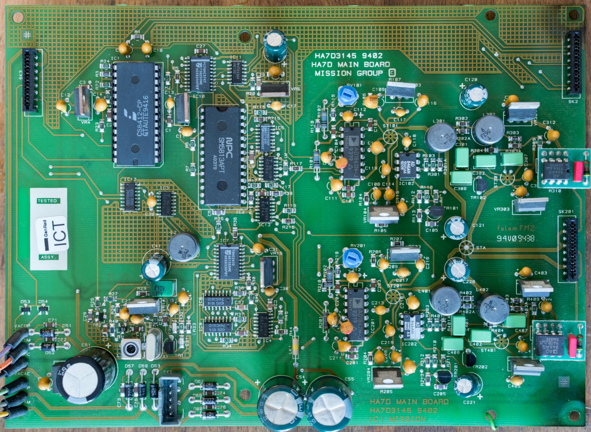
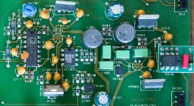
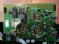
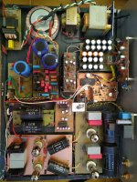
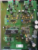
I found a defective and cheap Dacmaster online, bought it and repaired it, recapped it and upgraded the digital filter to a PMD100. This was the main PCB before recap:
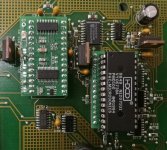
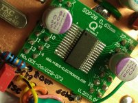
The Dacmaster sounds wonderful now and is really a good and nice and small devic. It has a nice analog section with very good AD1862 DAC chips:

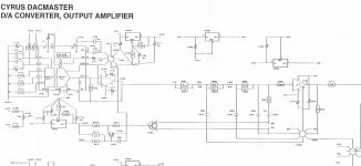
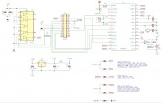
If somebody has a complete schematic I would be very glad to see it. I found only this part online:

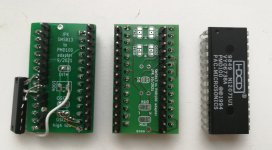
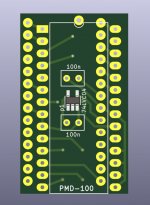
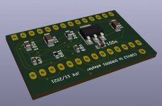
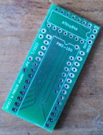
The adapter PCB has solder jumpers to configure the settings of the PMD and uses an inverter for the deglitch signal:

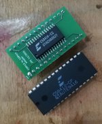
The first version of the PCB did not have the inverter on it, I soldered an old 7404 from my parts bin to the legs of the PMD (left PCB on this picture):
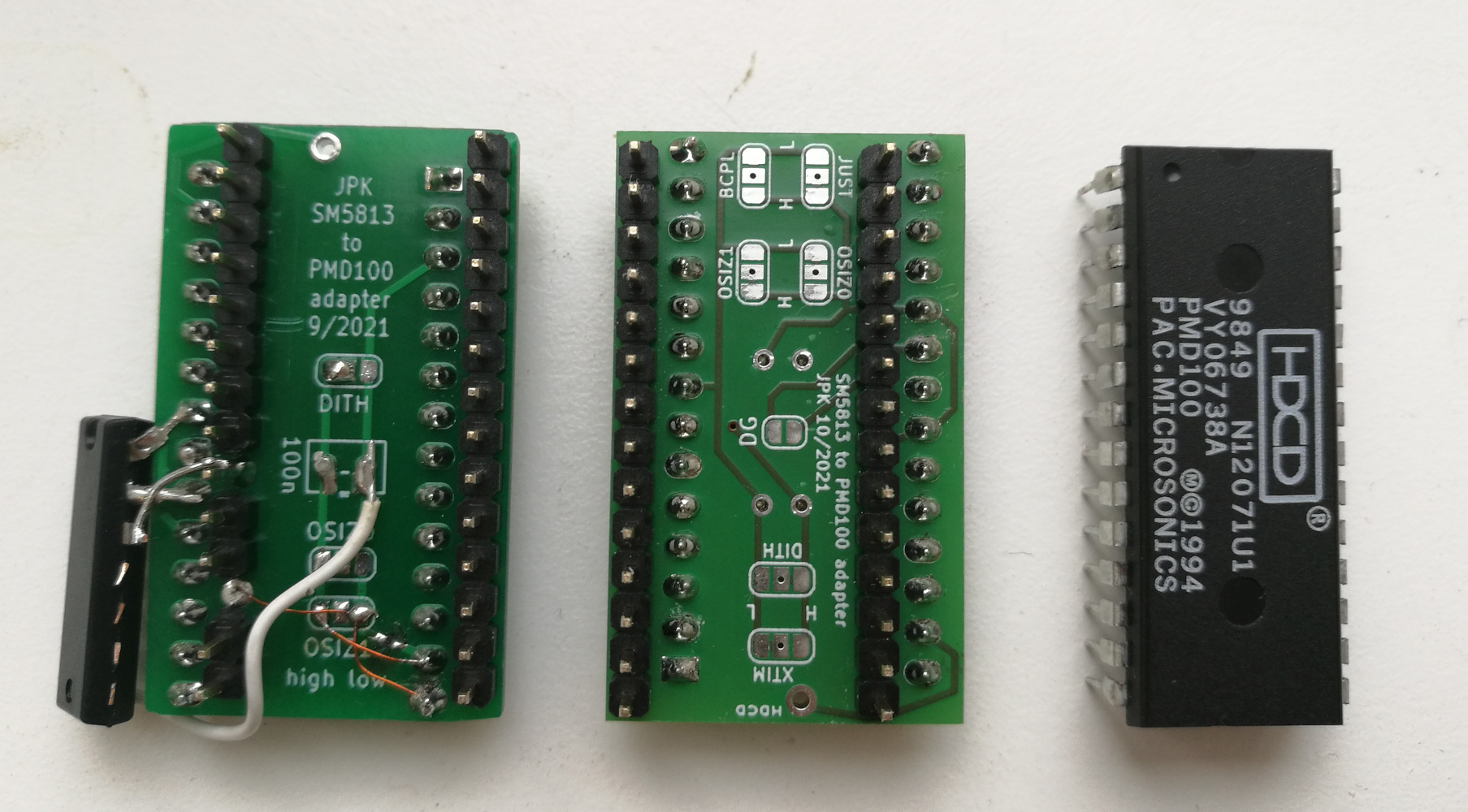
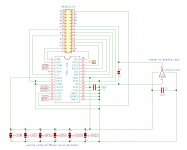
If anybody is interested I can give away the first version of the adapter PCB, and also I have 2 unpopulated PCBs of the final version (contact me via PM and I will send for free, I ask only for shipping cost). Here is the schematic of the adapter PCB:

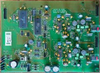
This is the board after recap and with the PMD100 fitted:

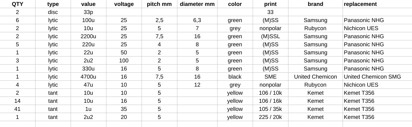
And this is my recap BOM for all 3 PCBs of the Dacmaster:
The sound improved a lot with the recap, and improved another leap with the PMD100: it sounds more fluid, more 3-dimensional, smoother, and also more emotional...
The Dacmaster sounds wonderful now and is really a good and nice and small devic. It has a nice analog section with very good AD1862 DAC chips:
If somebody has a complete schematic I would be very glad to see it. I found only this part online:
The adapter PCB has solder jumpers to configure the settings of the PMD and uses an inverter for the deglitch signal:
The first version of the PCB did not have the inverter on it, I soldered an old 7404 from my parts bin to the legs of the PMD (left PCB on this picture):
If anybody is interested I can give away the first version of the adapter PCB, and also I have 2 unpopulated PCBs of the final version (contact me via PM and I will send for free, I ask only for shipping cost). Here is the schematic of the adapter PCB:
This is the board after recap and with the PMD100 fitted:
And this is my recap BOM for all 3 PCBs of the Dacmaster:
The sound improved a lot with the recap, and improved another leap with the PMD100: it sounds more fluid, more 3-dimensional, smoother, and also more emotional...
Attachments
-
 before_recap.jpg554 KB · Views: 1,452
 -
 analog_section.jpg736.1 KB · Views: 1,238
 -
 schematic.jpg297.7 KB · Views: 1,139
 -
 pmd100_adapter.jpg215.4 KB · Views: 1,067
 -
 adapter.jpg582.4 KB · Views: 1,091
 -
 PCB.jpg123.2 KB · Views: 1,118
 -
 after_recap.jpg1,014.4 KB · Views: 1,129
 -
 recap_BOM.jpg120.7 KB · Views: 1,019
Last edited:
I made 2 adapter PCBs for the digital receiver: one for the CS8414 and one for the DIR9001 (based on the circuit shown here). The CS8414 adapter PCB has the loop filter components on the underside. The DIR9001 sounds much better than both the CS8412 and the CS8414. Maybe that's because of the extra regulator for the receiver chip...? I configured the jumpers on the DIR9001 and the PMD100 boards to 24bit left justified transfer between the two boards. Here are pictures:
Attachments
DIR9001 is simply better, the data says it all. I also replaced CS8414 with DIR9001 in my DAC, I left the regulators the same with two ADP7118 and I also use PMD100 as a dig filter. The sound is better and there is no doubt that DIR9001 is better than CS8414 (6).
And good work jpk73") , I am also a fan of old generation dac ic , now I will amplify in my two PCM1702 to 6 pieces, three per channel, it will be interesting to hear. And I intend to drive the TDA1547 soon.
, I am also a fan of old generation dac ic , now I will amplify in my two PCM1702 to 6 pieces, three per channel, it will be interesting to hear. And I intend to drive the TDA1547 soon.
And good work jpk73
, I am also a fan of old generation dac ic , now I will amplify in my two PCM1702 to 6 pieces, three per channel, it will be interesting to hear. And I intend to drive the TDA1547 soon.Attachments
Last edited:
It is very cool. It can be seen that JPK73 has put a lot of effort into verifying it. It is true that although DIR9001 only supports 96K, it does not prevent it from being a good-sounding receiving device. Congratulations.I made 2 adapter PCBs for the digital receiver: one for the CS8414 and one for the DIR9001 (based on the circuit shown here). The CS8414 adapter PCB has the loop filter components on the underside. The DIR9001 sounds much better than both the CS8412 and the CS8414. Maybe that's because of the extra regulator for the receiver chip...? I configured the jumpers on the DIR9001 and the PMD100 boards to 24bit left justified transfer between the two boards. Here are pictures:
I populated and installed the new board today, the sound improved a lot with dither mode 2. The following code runs on the ATtiny:
C#:
// for ATtiny84
// pin mapping clockwise
// set clock to 4MHz internal

// works with DIR9001 and PMD100 boards for Mission Cyrus Dacmaster

// change these settings to configure the PMD100:
byte oversampling_rate           =  3; // 1 = 2x oversampling, 2 = 4x oversampling, 3 = 8x oversampling
byte dither_mode                 =  2; // 0~7 = dither mode 0 to 7
byte input_data_justification    =  0; // 0 = left justified, 1 = right justified (16bit)
byte input_bit_clock_polarity    =  0; // 0 = rising edge, 1 = falling edge
byte input_frame_sync_polarity   =  0; // 0 = LRCI high means left channel, 1 = LRCI low means left channel
byte output_word_length          =  2; // 0 = 16bit, 1 = 18bit, 2 = 20bit, 3 = 24bit
byte output_format               =  0; // 0 = 2s compliment, 1 = COB
byte output_word_clock_polarity  =  0; // 0 = high to low at the end of the output word, 1 = low to high at the end of the output word
byte deglitch_low                = 31; // set falling edge of DG to 0~31st interval
byte deglitch_high               = 15; // set rising edge of DG to 0~31st interval
// end of settings

// pins:
byte MUTE  =  0;
byte MEN   =  1;
byte MDT   =  2;
byte MS3   =  3;
byte MS2   =  4;
byte MS1   =  5;
byte PROG  =  6;
byte XTIM  =  7;
byte LED   =  9;
byte DITH  =  8;
byte BTN   = 10; // can be used to wake-up the mcu

#include <avr/sleep.h>
#include "elapsedMillis.h"

elapsedMillis sleep_timer;
unsigned int sleep_interval = 500;   // mute ramp down takes 260ms, so 300 is a good value here

void setup() {
  delay(1000);
  pinMode(MEN, OUTPUT);
  pinMode(MDT, OUTPUT);
  pinMode(MS1, OUTPUT);
  pinMode(MS2, OUTPUT);
  pinMode(MS3, OUTPUT);
  pinMode(PROG, OUTPUT);
  pinMode(MUTE, OUTPUT);
  pinMode(LED, OUTPUT);
  pinMode(DITH, OUTPUT);
  pinMode(XTIM, OUTPUT);
  pinMode(BTN, INPUT_PULLUP);
  delay(100);
  digitalWrite(DITH, HIGH);
  digitalWrite(XTIM, LOW);
  digitalWrite(MUTE, HIGH);
  digitalWrite(LED, LOW);
  digitalWrite(MEN, HIGH);
  digitalWrite(MDT, LOW);
  digitalWrite(MS1, LOW);
  digitalWrite(MS2, LOW);
  digitalWrite(MS3, LOW);
  delay(100);
  digitalWrite(PROG, HIGH);
  delay(100);
  configurePMD100();
  delay(100);
  zeroAttenuationPMD100();
  delay(3000);
  digitalWrite(MUTE, LOW);
  sleep_timer = 0;
}

uint32_t value = 0;

void configurePMD100() {
  value = 0;
  value |= uint32_t(dither_mode) << 19;
  value |= uint32_t(output_word_length) << 17;
  value |= uint32_t(input_frame_sync_polarity) << 16;
  value |= uint32_t(deglitch_high) << 11;
  value |= uint32_t(deglitch_low) << 6;
  value |= uint32_t(output_format) << 5;
  value |= uint32_t(output_word_clock_polarity) << 4;
  value |= uint32_t(input_data_justification) << 3;
  value |= uint32_t(input_bit_clock_polarity) << 2;
  value |= uint32_t(oversampling_rate);

  for (int i = 0; i < 24; i++) {
    digitalWrite(MEN, LOW);
    digitalWrite(MDT, bitRead(value, i));
    delayMicroseconds(1);
    digitalWrite(MEN, HIGH);
    delayMicroseconds(1);
  }

  digitalWrite(MDT, LOW);
  delayMicroseconds(4);

  digitalWrite(MS2, HIGH);
  digitalWrite(MS3, HIGH);
  delayMicroseconds(1);

  digitalWrite(MEN, LOW);
  delayMicroseconds(1);
  digitalWrite(MEN, HIGH);

  delayMicroseconds(2);
  digitalWrite(MS2, LOW);
  digitalWrite(MS3, LOW);
}

void zeroAttenuationPMD100() {
  digitalWrite(MS1, HIGH);
  digitalWrite(MS2, HIGH);
  delayMicroseconds(1);
  digitalWrite(MEN, LOW);
  delayMicroseconds(1);
  digitalWrite(MEN, HIGH);
  delayMicroseconds(1);
  digitalWrite(MS1, LOW);
  digitalWrite(MS2, LOW);
}

void loop() {
  if (sleep_timer > sleep_interval) {gotoSleep();}
}

void gotoSleep() {
  GIMSK |= _BV(PCIE0);
  GIMSK |= _BV(PCIE1);
  PCMSK1 |= _BV(PCINT8);                  // use PB0 as interrupt pin
  ADCSRA &= ~_BV(ADEN);                   // ADC off
  set_sleep_mode(SLEEP_MODE_PWR_DOWN);    // replaces above statement
  sleep_enable();                         // sets the sleep enable bit in the MCUCR register (SE BIT)
  sleep_cpu();                            // sleep
  sleep_disable();                        // clear SE bit
  PCMSK1 &= ~_BV(PCINT8);                 // turn off PB0 as interrupt pin
  ADCSRA |= _BV(ADEN);                    // ADC on
  sleep_timer = 0;
}

ISR(PCINT1_vect) {sleep_timer = 0;}
Attachments
Last edited:
- Home
- Source & Line
- Digital Line Level
- modifying Cyrus DACMaster