Hi linuxworks,
I would be interested in a board and a parts list 🙂 The box I linked has arrived now, but does not do 192 Khz. It works fine at 96KHz so if your board does 192 Khz, 24 bits it would definitely be preferable.
I guess it would also be a good idea to duplicate the output (like the box I linked to) so we can test DAC alternatives.
Currently I am only interested in optical connections, as they have the advantage of no ground loops. Am I missing some thing thats better about Coax?
good luck
Owen
What you're missing about coax is that it has a wider bandwidth than Toslink.
192/24 audio is really pushing the limits of Toslink at 9.2 MB/s. The bandwidth of Toslink is 5-6 MB/s with plastic optical cables and 10 MB/s with high purity quartz optical cables (source: Wikipedia).
192/24 audio is really pushing the limits of Toslink at 9.2 MB/s. The bandwidth of Toslink is 5-6 MB/s with plastic optical cables and 10 MB/s with high purity quartz optical cables (source: Wikipedia).
Last edited:
according to specs found on mouser/digikey, some toslink blocks go up to 15mhz and some even to 25.
coax is preferred at 192k but newer toslink parts should work too, at least if you can believe the frequency specs of the more modern toslink parts.
coax is preferred at 192k but newer toslink parts should work too, at least if you can believe the frequency specs of the more modern toslink parts.
At €38, the switchbox will probably have bog standard Toslink receivers and transmitter (or clones), and I doubt they'll be able to handle 192/24.
Note that I was using megabyte per second in my previous post, not megahertz.
Note that I was using megabyte per second in my previous post, not megahertz.
seems to be 'conventional wisdom' to use coax for 192k and keep opto at 96k or below (or even stay at 48k and below).
I don't believe 16/20/24 bits changes things; only the sample-rate (is that correct?)
I don't believe 16/20/24 bits changes things; only the sample-rate (is that correct?)
Correction, I was writing MB/s but it should be MHz instead.
The needed bandwidth is calculated as follows:
sampling rate (Hz) x resolution (bits) x number of channels = bandwidth (Hz).
This means the resolution as well as sampling rate affect the needed bandwidth:
e.g.
44,100 x 16 x 2 = 1.41 MHz
and
192,000 x 16 x 2 = 6.14 MHz
192,000 x 20 x 2 = 7.68 MHz
192,000 x 24 x 2 = 9.22 MHz
Last edited:
in spdif, I'm not sure that's correct. I was under the impression that 16 vs 20 bits is an issue of padding with 0's but not taking any more or less room than either of them.
then, for 24bits, that's 'aux data' and again, that's always in the payload whether its mapped to user data or extra audio word data.
I guess one way to test this is to inject known 16bit and known 20bit audio into the wire and see it on a storage scope. does the higher 20bit stream seem to run at a faster rate? I really don't think it does but I may be wrong.
Last edited:
SPDIF is always 32 bit per channel = 64 for a frame (both channels). In older equipment only the first 20 are used, 4 are for "future use", rest are used for syncronization. It will add zeroes for a 16 bit source. For newer equipments it can carry audio at full 24 bit (extra 4 bits ignored on older receivers).
http://en.wikipedia.org/wiki/AES3#The_Protocol
And for optical, the cable needs to support that bandwidth too. 98% of the "audio" optical cables are plastic, not capable of 192kHz. It might work for shorter than 1m ones...
http://en.wikipedia.org/wiki/AES3#The_Protocol
And for optical, the cable needs to support that bandwidth too. 98% of the "audio" optical cables are plastic, not capable of 192kHz. It might work for shorter than 1m ones...
Last edited:
I was with you until that last part about plastic.
you do know, I'm sure, that toslink is ONLY spec'd for 'cheap plastic' and that the world has been using 'cheap plastic' pretty successfully for decades, now, even with pro audio adat using 'cheap plastic fiber' ?
if you use the right toslink blocks and keep the toslink cable somewhat short (6' or so? something shorter than 25' surely) 192k works ok over fiber, with some caveats. I've personally done it and the bits get there.
BUT you should be using relockers, though (imho) with any physical transport. I'm pretty into the wm8805 series reclocker chips, at the moment, and they'll 'snap' the bits back to alignment pretty well. sort of like a layer1 repeater vs layer2 bridge. the retiming effect is analogous.
how is this project going?
I've been a little lazy on this project as its working pretty well at the physical level; I have just not finished the firmware to talk to the wm8805 chip. I have code in place but have not spent time debugging it, yet. I mostly wanted to USE the chip for a while and see if I liked it and if it had any unpleasant side-effects. so far, after listening for several months, I'm pretty happy with it as an spdif receiver. I am planning on using it in a finished design.
the direction I'm thinking of going on my spdif switch is a bit of a hybrid approach. instead of doing the switching with this chip, I might just use it in 'dumb mode' (for the time being) where it has 1 input and 1 output. I can do the switching with simple ttl muxes ahead of the chip and this has the benefit of being able to completely remove the reclocker, on command, if you want to (or even need to). if the WM chip does the switching, you're forced to always route thru it.
I'm also thinking of making my spdif switch a bit bigger in scope. an spdif receiver has the option of decoding to i2s or re-encoding to spdif again (the reclock feature). I've recently been playing with 'affordable and easy' DAC chips and I'm thinking of simply adding one of these easy dac chips to the output of the i2s lines on the spdif 'switch'. its minimal cost and parts count.
the other thing I'm going to add is a dual switch feature. think of it as a digital version of a 'monitor' and a 'record' output. you can record one spdif source and listen to another (like tape loops and EPL loops of the old days) 😉 this is another reason I want to use simple TTL for spdif switching; I can have 2 of these for very little extra cost and board space and give the user lots of flexibility in his output routing. this would be something like a 4input 2output switch. one output would be switched spdif for 'record' and the other output would be a choice of analog (via that dac) or digital via the 2nd gang of the spdif switch.
I am not good at diagram drawing (lol) but this might illustrate what I'm shooting for, now:
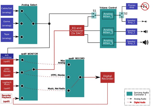
this drawing is already out of date with my latest revision but its close enough for now. the bottom 2 teal 'boxes' are the 2 gangs of the spdif switch. 3 of the digital inputs are mirrored between the 2 switches with the recorder-playback not present on the last box, for hopefully obvious reasons 😉 not shown is the 'affordable dac' box but it would logically live in the 'spdif monitor' teal box, at the red switched output line.
this whole diagram is part of my overall preamp design; it incorporates analog switching and pathing as well as spdif where applicable. the spdif/dac box will be a separate chassis from the analog preamp-switch box. (for those who care, the EQ/XO is a behringer deq/dcx 2496 pair running active XO and 2 or 3 amps).
There is NO reclocking done in the WM8805. That crystal clock shown is for something else.I'm pretty into the wm8805 series reclocker chips, at the moment, and they'll 'snap' the bits back to alignment pretty well. sort of like a layer1 repeater vs layer2 bridge. the retiming effect is analogous.
no reclocking? the output is supposed to be 40ps of jitter or less, as long as the input locks to it. their sheet starts out saying:
"a pass thru option is provided which allows the device simply to be used to clean up (de-jitter) the received digital audio signals"
is that not reclocking? how do you define reclocking?
"a pass thru option is provided which allows the device simply to be used to clean up (de-jitter) the received digital audio signals"
is that not reclocking? how do you define reclocking?
fwiw, the way I tested 192k over toslink was with simple gear I had at home: an asus xonar ds (has a 192k grade toslink sender block on its rear tab) and an amb gamma1 dac that I know, for a fact, has a 192k grade toslink block (I built my copy and I know the schematic fairly well, lol). I set my linux box to force resample up to 192k (with some pulse audio .conf file magic) and played music. the green light on the dac locked and music came out. I sent that stream into a dac that I knew could 'only' do 24/96 and that dac would not lock. leaving the cable alone, I re-edited the linux conf file (forcing sampling to 96k, say), restarted pulse audio, replayed music and the 'old' dac played fine. the gamma1 dac would still play that 96k stream too. using some cheap no-name toslink connect.
it works. bits get there. you can argue its jitter, but bits do definitely get there 😉
it works. bits get there. you can argue its jitter, but bits do definitely get there 😉
Last edited:
Nobody says that it doesn't "work" as receiver. You just need to understand that nowhere on datasheet is mentioned any "reclocking", it just does not reclock.
"De-jitter" is done by the analog PLL loop and involved timing constants. Crystal clock is used only when there is no PLL lock onto incomming signal. In free running mode you have 50ps jitter. But if you have that PLL "lock", the output frequency will have jitter resulted from the incoming one. If incoming has 500nS on low frecuency, that's what you will have on the output. If it has a higher frequency jitter, that will be attenuated by the PLL loop - any SPDIF receiver works that way.
Is that relevant for PC HDD originating signals? Don't know how much jitter have those compared with a stand-alone optical transport.
Assuming anything else is just... assuming.
Last edited:
there is not a lot of internals in the data sheet, so there is a limit as to how far we can see into this chip.
I was only implying what they state explicitly. I don't pretend to know how they do it, but if they are not *ensuring* 50ps of jitter at the output, then things seem a bit misleading.
are you suggesting they are misleading on purpose?
they also do say 'de-jitter'. not imply, but say.
so, I'm not sure what to think. we have you saying it does not do this and we have the vendor saying they do.
??
"De-jitter" not equal with "reclocking". Show me where in the whole data sheet is mentioned such thing.
Any digital receive will claim "cleaning the signal" and "de-jitter" - and that is true to an extent, for high frequency jitter, due to the PLL loops used for recovery of embedded clock.
WM don't mislead, but the first page of any datasheet is just a big ad. You need to read the whole datasheet... 50pS is for the "intrinsic jitter", not "recovered jitter" - that means is for the transmitter function, when crystal and not the PLL loop is used as source.
Last edited:
I wonder how the cirrus 8412/14/16 compares to the wolfson? the cirrus (crystal, when I first used the 8412) does not use a crystal (lol) but the wolfson does.
reading the data sheet, it seems the routing can have the recovered clock from the stream or from the xtal. what is the purpose of the xtal, in your understanding, if its not used to help align the audio data to it?
and I'm not sure that any receiver claims to de-jitter. does cirrus? I have not seem them make claims of this sort at all. in fact, their receivers tend to be sensitive to jitter, if anything.
btw, let me ask you - you seem to have a bone to pick with this chip or company. care to explain? have you actually measured the before/after effect of this chip? I have not (yet) and I may not be able to and so I have to trust the vendor in what they say. if you have data that suggests or shows this chip not to be what it represents, please show it.
but clearly, they are suggesting they clean the signal up from hundreds down to ten's. if you do have data that shows this to be false, I would love to see it.
I am late to the party, but with all those nice diy dacs with maybe one or two inputs, and a slew of equipment with coax digital out, it would be really handy to do a coax switching circuit to connect in front of the dac.
I am not fond of optical out, so it should be a coax solution.
I saw that linuxworks implemented a solution with pulse-transformers, but I am not sure I understand why they are needed? Is it just to achieve isolation, or are they necessary because of impedance mismatch?
I am not fond of optical out, so it should be a coax solution.
I saw that linuxworks implemented a solution with pulse-transformers, but I am not sure I understand why they are needed? Is it just to achieve isolation, or are they necessary because of impedance mismatch?
the pulse trafos are usually there for isolation. its good to have it on both the sender and receiver since you may connect to some other box that has NO isolation. having double is not a problem and having one, at least, is minimal.
I've seen a lot of the isolation ruined by taking one end of the trafo (its 'outside' winding) and grounding it on the local chassis. that chassis is usually earth connected and so you are no longer floating - when going to 2 boxes like that. so I usually like to have a good strong buffer drive the trafo and have the secondary wiring go directly to the output jack (rca, bnc, etc). a 75ohm R is often added on that output, but it could be a 90ohm or other value; so that the measured Z is 75, effectively.
as for the switching of inputs, some dacs have controllable input select and some don't. for those that don't, you can front-end the dac with a digital switch, and I do that quite a lot, myself, so I consider that an easy way to add remote control to a dac that didn't come with it. if you can have the dac control its input select, then that's very ideal; but if that dac is manual-only and its not practical to modify it, adding a switch in front of it is the next best thing. and also from a 'management' point of view, if you have to script or automate remote control of your system, you only have to teach your system about that spdif switch once and if you want to change out the dac as dacs come and go, you can and it won't affect the remote control system. keeping that function separate from the decode function makes some sense, in that light.
- Status
- Not open for further replies.
- Home
- Source & Line
- Digital Line Level
- diy Optical SPDIF Switch?