I just do not understand what so much "noise" and contradictory theoretical discussions... Is not more easy, and more reasonable from your part merce, quasp to just try yourself this solution on yours gears? One do not need to try with expensive caps. Just solder some normal caps near to the chip and hear the result. If it may be something you like, then try with better caps, bigger capacity, and maybe such "construction", as I did.
I have nothing against critics and discussions, but I can observe that in this case it happen something special. Someone, who never ever come out with a practical solution, a picture or a even a sketch of theirs ideas, about something or another in this field, come out systematically with only critics to somebody else, who actually do it practical things, experiment and experience something, try to find better solutions, and publish here some results.
You have something against this solution published here. That`s right! But you have nothing to support with your opposition. Only assertions. Do you really think that I soldered together some components, took a picture and published it here to be famous?
You wrong! I do not care about such and I do not need it.
I experienced about something, and I think to share that with somebody else, who may eventually be interested in the same, or may need a better idea for his experiments, in the way to find that "best of"...
There is not here the place (in my opinion) for contest; who know best and most about everything. I can not even see that it may be a reward for this... But it may be a place where one or another it may share his ideas for the benefit of the others.
I know that I may not explain very well about things, but I know very well what I'm doing. I published those things here because I experienced about, and I had positive results this way. Somebody doubt about? Is OK. Come out and critic. Is this OK too. But try it first to know what you critic about...
In one way it is enough funny all this here... It were happen nothing in this thread for many months. I could never ever see quasp or somebody else coming in this time and publish something in the subject of this thread, or heaving a what so ever (professional) contribution. But after I have published this last picture, it come out suddenly the professionals with "opinions" about how stupid this it may be, how wrong is, how this not even work at all, and so on... Isn't it this funny?
Last edited:
I believe most now know my views on clock modifications, the majority I believe cause more problems than they solve. This is not me being evil, mean or nasty, but stems from the work I do on PCBs regarding signal integrity EMC etc. Same with decoupling, there is a wealth of info out there.
I have had a brief look around the ESS site and data last night, there is a good publication on how to improve the DACs working conditions, I will try and get some daqta sheets, or if someone has them I would appreciate it.
RayCtechs wide ball comment is a bit strange, as we are talking about decoupling the avcc pins of a DAC device!
I believe most now know my views on clock modifications, the majority I believe cause more problems than they solve. This is not me being evil, mean or nasty, but stems from the work I do on PCBs regarding signal integrity EMC etc. Same with decoupling, there is a wealth of info out there.
I have had a brief look around the ESS site and data last night, there is a good publication on how to improve the DACs working conditions, I will try and get some daqta sheets, or if someone has them I would appreciate it.
RayCtechs wide ball comment is a bit strange, as we are talking about decoupling the avcc pins of a DAC device!
I do not doubt about your competence in this field, and I will not discuss this. As you maybe know already there are thing in this universe which are not all the time exactly as we believe, have learned about, knows or are use with. What is wrong with trying new ways? If it may be wrong way, then record that and correct, if not then it is a benefit to find a better/new way...
Good to know that you decided to take a closer look on this subject.
I personally think that is a benefit to hear sometime what others have to say first, than just reject everything which is not in the template one are use with for long time, or by other reasons...
You may PM me to send you the datasheet of the chip.
PS. Some more details about the last picture. One may have impression of a quite long connecting wires. The picture is enough enlarged. In real the length of connections is between 2 and 3 mm. There is much better connections than the PCB traces. The wires are silver and bigger section than the traces. The routing of the wires it may be even improved. It is to be seen in the picture a ground plane under the caps (over the chip)...
Last edited:
Coris, I ask questions and sometimes post a comment. And most of what I do is to promote discussion and try to get the persons view and beliefs on what they are doing. It is not only here, but at work I do work for numerous EE's and quite often you will get strange request, I will then question the request and if I disagree, will say so. I have always questioned what not only other do but myself, and question my own views and belief's more than I do others, thus I learn and my views change... nothing personal or malicious")
As to clocks, don't take it as personal, it is a general comment and view I have, usually when someone replaces a perfectly adequate clock with one on the end of 6" of single core wire.
My main concern would be the increase in inductance with the wires.
I have sent a PM.
Cheers and Beers
As to clocks, don't take it as personal, it is a general comment and view I have, usually when someone replaces a perfectly adequate clock with one on the end of 6" of single core wire.
My main concern would be the increase in inductance with the wires.
I have sent a PM.
Cheers and Beers
I really do not know what you refer to about that clock at the end of a 6" single core wire...
It may be a misunderstanding here. Have you seen something like this in the pictures I have published? Or I have claimed that a such configuration is something reasonable?
I just sustained the opposite about long clock traces. As you may see in one of my pictures, I have soldered the oscillator output directly to the chip pin...
A little bit confused about this subject...
There was nothing personal or aimed at you, it was a general comment.
It is all right. But the comment have nothing to do with the subject, my interventions/contributions in this thread...
Anyway, we may consider closed this aspect.
It is definitely the large decoupling capacities with increase quite dramatic the analogue/sonic performances of the ES9018 DAC chip.
In the last time I have increased the AVCC decoupling on both side of the chip from 800µF/side to 4200µF/side. The lowest level of the low end frequencies of the sounds are not only good hearable now, but it can be good feel it actually. In the same time the increasing of the resolution and details in sounds in the high end of the audio spectre, is also remarkable. The dynamics of the sound is also much improved. This is quite a special experience at last...
I have used this time quite common, but low ESR aluminium caps soldered directly to the chip pins. Low noise voltage regulator for AVCC, at 3,8V. The DAC is running by a 108Mhz clock. This clock frequency is lower than I have used before. The reason is that this frequency is divided further for another functions, but not because the 125Mhz which I have used earlier it were not a well working frequency. I`m actually excited to try again 125Mhz in this quite large decoupling setup...
May I ask you the following points?
1. How many times you have ever turned the power of the system on/off ever?
2. Have you observed a voltage change profile at an AVCC pin of the DAC chip by an oscilloscope at timings of power on/off?
3. What measures have you taken in order to discharge the cap after power off and to mitigate a possible high rush current at power on?
4. What kind of regulator do you use and how is the capacitance value of decoupling capacitors placed at the input side of the regulator?
Hi Bunpei
Thanks for following yet this thread.
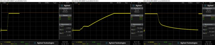
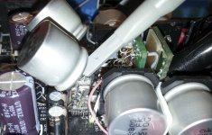
I just turned on/off many times my system to make some pictures of the AVCC. You may see the snapshots her... There is another picture with the measured environment (it may not looks very nice, but is an experimenting area...) So, the nr. 2 question is answered...
The question nr. 3 is partial answered too. The high rush current at power on is fixed by the regulator current protection.
The regulator is LT1763, and the filtering caps before this regulator are of teens of mF.
Of course if is about using even larger capacities on this AVCC, one may take some special steps to take care of possible issues you may thinking about when asking the questions above.
Else you are welcome with another questions too... Or maybe give it a try to this idea...
Thanks for following yet this thread.
I just turned on/off many times my system to make some pictures of the AVCC. You may see the snapshots her... There is another picture with the measured environment (it may not looks very nice, but is an experimenting area...) So, the nr. 2 question is answered...
The question nr. 3 is partial answered too. The high rush current at power on is fixed by the regulator current protection.
The regulator is LT1763, and the filtering caps before this regulator are of teens of mF.
Of course if is about using even larger capacities on this AVCC, one may take some special steps to take care of possible issues you may thinking about when asking the questions above.
Else you are welcome with another questions too... Or maybe give it a try to this idea...
Attachments
Last edited:
... The regulator is LT1763, and the filtering caps before this regulator are of teens of mF. ...
Hi, Coris!
I much appreciated your very detailed answers!
Would you tell me just one point for clarification?
Does the expression "teens of mF" mean,for example, "15,000 micro F"?
Bunpei
BTW, there is only one AVCC regulator, so it sees 8400 µF on its output in this setup...
The funny part are that by stepping up the PSU you will get improved fidelity and it have virtually no end..
When I simulated PSUs in the ´80´s and ´90´s there was no limits, but for every time you increase the capacitors like the ones in your AVCC circuit it just attenuates the noise spectrum down to a lower frequency.
After a lot of simulations and practical testing and measuring I decided on a goal of 0.008Hz for the PSUs. Not because it is the optimal or limit, but because it was possible to implement practically and I did not want to waste more time on this subject.
If it runs 10mA in your 3.8V AVCC circuit then my "rules" would require 52.000uF. 100mA and then 520.000uF. If you use 0.08Hz (0.1Hz) as a goal then 5.200uF and 52.000uF.
As the ES9018 chips uses an 0.1Hz filter constant regarding jitter rejection then the PSUs should optimally be clean down to a factor below 0.1Hz to not compromise the jitter removal circuits...
You have two 1.2V and one 3.3V DVCC voltages that need to be improved for optimum performance of your DAC as the digital filtering and jitter removal circuits are found here.
Much appreciated your details RayCtech
It make sense to me your experiments and conclusions. I would like to go further with increasing the AVCC, but lack of informations in this area make me to be more carefully. I think I will take the risk one day... I will for sure experiment more in this.
Is quite difficult to describe with words how the sound sounds with these large capacities. The fidelity is amazing. I can well hear details, I have never been aware about in records I played. I just wonder how my speakers (not very special ones) can reproduce such details... Is quite fascinating... It looks to me that this DAC chip is so elaborate that even its designers themselves were/are not really aware about what actually it can do...
Last edited:
Hi, Coris!
I much appreciated your very detailed answers!
Would you tell me just one point for clarification?
Does the expression "teens of mF" mean,for example, "15,000 micro F"?
Bunpei
You welcome.
As total is about more than 30 000µF...
Today I have got some better caps (Nichicon oscon, 12mOhm ESR), and smaller as physical dimension.
Now I have 6200µ on each side of the chip (AVCC). So 12400µ as total on the same regulator.
There is an even higher improvement, but more sophisticated as result. I can say that are few sides of the improvements in sound quality. On one side is a very high fydelity. This was increasing as the decoupling capacities were increased. So RayCtech may have right at the improvements are more an more as the decoupling capacity increase on AVCC.
Another aspect of the improvement is the sound stage. Here is about definition/resolution of the components sound (instruments) in the sound stage. With my earlier caps, I was not very satisfied with how the perception of the sound stage components it were distributed. I could hear very clear that the sounds came out from the speakers on sides, and (were the recording was a higher quality), few positions in the centre of the stage. The Nichicon oscon caps I have mounted today have changed quite much the things (stages components). More distinct positions, and more "sources" of sounds from the different components of the sound stage. A better distribution (accordingly to the original positions of the instruments at recording) between the two channels/speakers.
It could be interesting that observations/tests are made after every components change. But who have so much patience for so analytic testing?
Now, at last I can not say very precise where it may come from the improvements in my experiments with these large decoupling capacities. It may be because I have used at last better quality caps, or because the even bigger capacities. Or it may be both...
Anyway, I may say that is very special to experience such high fidelity. Even more interesting is that one can find/hear fidelity increasing at quite banal (mid quality) recordings. I have some such recordings which it were streamed over internet as mp3 files, 256Kbps 44,1Khz, and so. After a quite simple treatment (upsampling on 64bit, converted to FLAC) I can notice quality/fidelity increasing for such files played out through improved ES9018 hardware. My understanding /conclusion is that very much of the quality audio informations still be inside these heavy compressed files, or are not lost at all. The only one it need is a device which it can bring out with extreme fidelity all or as much as possible of the recorded informations.
At last this it is really what we (many of us) are doing experimenting in this field: bring it back as much as possible of the informations stored inside these audio files.
Last edited:
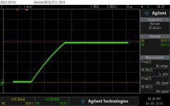
Finally experimented with a very large capacity to decouple the AVCC of ES9018: 0,4F.
As RayCtech pointed above out, the increasing in sound fidelity is now even more than before at the device outputs. The presence of the sound elements is just remarkable. All the sounds in soundscene it come more in front of the listener, more into the room.
I have took the risk and connected directly this huge capacity after the LT6317. Well, separated previously from the DAC chip... Just no any problem for the regulator to accept such cap on its output. After approx 5s the cap is charged and the regulated tension level very stable. It take almost a minute to be discharged, after power off...
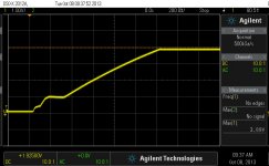
There is pictured here the start up sequence with this cap, and beside for comparative reasons, the previous start up snapshot of an approx 5000µ decoupling cap.
An interesting observation with this huge AVCC capacity: In power off sequence, the very stable regulator tension it rise up with approx 10mV, before the cap discharge process starts and goes low very slowly. The decoupling cap is connected directly to the AVCC pins of the DAC chip.
This slightly rising of the regulated tension when the chip it loose the another power rails, I explained as the AVCC line of ES9018 it is completely decoupled from the power source, or do not show any load for the regulator. It is like a relay contact which is switched off into the chip, and it cut completely off the AVCC load from the power source. Then, after a second or two it start the cap discharging curve.
I have also noticed, looking at these start up sequences pictured here, that in case of a 5000µF at the AVCC regulator output (with the chip connected), the regulator`s current protection it is working (stair in the ramp up). This protection seems to have a different behaviour in case of this 0,4F cap on regulator output. So far I do not have any interpretation for this behaviour... Anybody with a explanation is welcome.
As RayCtech pointed above out, the increasing in sound fidelity is now even more than before at the device outputs. The presence of the sound elements is just remarkable. All the sounds in soundscene it come more in front of the listener, more into the room.
I have took the risk and connected directly this huge capacity after the LT6317. Well, separated previously from the DAC chip... Just no any problem for the regulator to accept such cap on its output. After approx 5s the cap is charged and the regulated tension level very stable. It take almost a minute to be discharged, after power off...
There is pictured here the start up sequence with this cap, and beside for comparative reasons, the previous start up snapshot of an approx 5000µ decoupling cap.
An interesting observation with this huge AVCC capacity: In power off sequence, the very stable regulator tension it rise up with approx 10mV, before the cap discharge process starts and goes low very slowly. The decoupling cap is connected directly to the AVCC pins of the DAC chip.
This slightly rising of the regulated tension when the chip it loose the another power rails, I explained as the AVCC line of ES9018 it is completely decoupled from the power source, or do not show any load for the regulator. It is like a relay contact which is switched off into the chip, and it cut completely off the AVCC load from the power source. Then, after a second or two it start the cap discharging curve.
I have also noticed, looking at these start up sequences pictured here, that in case of a 5000µF at the AVCC regulator output (with the chip connected), the regulator`s current protection it is working (stair in the ramp up). This protection seems to have a different behaviour in case of this 0,4F cap on regulator output. So far I do not have any interpretation for this behaviour... Anybody with a explanation is welcome.
Attachments
Last edited:
- Home
- Source & Line
- Digital Line Level
- ESS9018 - try new, try more...