make sure its 50ohms if you use coax. i suggest using hirose u.fl connector system, it can be quite easily fitted to anywhere that has the clock and ground available near each other, you do not necessarily have to have the correct pads. alternatively you can use LVDS
Thanks for advise! I have already a such 50 ohm coax (0,81mm) but not yet connectors for it... I will find a solution to try this in the next days...
... May I ask how you`ve generated that PCM file? ...
Hi, Coris,
I'm sorry that I missed my answer to your question.
I used this Japanese freeware "WaveGene" provided by "efu".
WaveGene Download
As the highest sampling frequency available in my environment was limited to 192kHz, I made a trick. First, 176.4 kHz source was generated and the sampling frequency value in its WAV header was edited to represent 352.8 kHz.
I`ve done it (Bunpei)! I tried at least synchronous clock for ESS9018 in my system.
I`ve coupled directly the master clock (25Mhz) to the clock input to the DAC chip. The coax cable were at last 25cm long... Too long! Not happy at all about this length of the cable, but was not possible shorter in my actual hardware configuration.
It just worked very fine at least! But... No conversion for the 192khz sampling files... Else, for the rest of all samplings spectre, it was running just excellent. I could register a slightly increasing in details in the sound stage. I think it could be better result if I should have a shorter clock path between those devices. I`m quite sure that is an enough high potential in this kind of clocking ESS9018. I would like to repeat this experience with a very short path for the synchronous clock. I think I will try again on Buffalo platform, and with an enough high clock frequency to make possible 192khz samplings conversions.
Now a question for Bunpei. What is the advantage to have two ESS9018 chips (two paralleled Buffalos) in the configuration you use for the moment?
In my opinion it have to be better to have all the channels of a DAC chip coupled together (mono), and have two such mono configurations for stereo. As I understood, Bunpei use two ESS9018 in stereo configuration coupled in parallel: two of left and right channels from two DACs coupled together.
Why I mean is better double mono configurations for stereo? I do think that is not very possible to have two identical ESS9018 chips out from production. So it have to be a very slightly difference in between two chips parameters. Coupling together 2x Left & 2x Right from two different chips, which are not at all identical (for not say more about the components around those chips) could not bring the best result. But having two slightly different (parameters) in a double mono configuration (two stereo channels) is more bearable for the resulting stereo sound... I do hope I`ve succeed to explain well enough what I mean...
So, at least, I `m back to may clock winner: 112,896Mhz for ESS9018 in my present (asynchronous) system. I think I will (definitely?) close this Oppo95 box and go back to continuing/finishing pouting together the Buffalo system...
Last edited:
Now a question for Bunpei. What is the advantage to have two ESS9018 chips (two paralleled Buffalos) in the configuration you use for the moment?
In my opinion it have to be better to have all the channels of a DAC chip coupled together (mono), and have two such mono configurations for stereo. As I understood, Bunpei use two ESS9018 in stereo configuration coupled in parallel: two of left and right channels from two DACs coupled together.
Why I mean is better double mono configurations for stereo? I do think that is not very possible to have two identical ESS9018 chips out from production. So it have to be a very slightly difference in between two chips parameters. Coupling together 2x Left & 2x Right from two different chips, which are not at all identical (for not say more about the components around those chips) could not bring the best result. But having two slightly different (parameters) in a double mono configuration (two stereo channels) is more bearable for the resulting stereo sound... I do hope I`ve succeed to explain well enough what I mean...
Dear Coris,
Have you actually consider a physical alignment of two Buffalo III boards with one I/V module? If you would think of it once, you would have found some merits on the idea of stacking two Buffalo III boards in a vertical direction.
When you say "8 channel mono", it's not easy to sum up two group of 4 channels on each side of the DAC chip with neat wiring.
Bunpei
OK! I get your point...
What so special about this part
Bunpei
Whats so special about this part that NDK was not able to make before without TAD's involvement ?
What is the closest NDK series to this one ?
What do you guys think about this ?
Zegar wersja MK II hybryd
MRelektronik.pl
lampizator.freeforums.org • View topic - superclock
I heard that the device was a custom part co-developed by TAD and NDK. I have never found it on NDK's product listing published on their web site.
Moreover, the low phase noise profile must be achieved by its associated power supply module. The black box left to the main player box is a dedicated power supply unit.
An externally hosted image should be here but it was not working when we last tested it.
Bunpei
Whats so special about this part that NDK was not able to make before without TAD's involvement ?
What is the closest NDK series to this one ?
What do you guys think about this ?
Zegar wersja MK II hybryd
MRelektronik.pl
lampizator.freeforums.org • View topic - superclock
Bunpei
Whats so special about this part that NDK was not able to make before without TAD's involvement ?
What is the closest NDK series to this one ?
What do you guys think about this ?
Zegar wersja MK II hybryd
I looked at the picture of Zegar wersja MK II hybryd. The shape made me remember NDK TCXO like this;
5920A-AQJ70(Fixed Communication)/Temperature Compensated Crystal Oscillator (TCXO)/NDK
On the other hand, the oscillator employed in TAD-D600 is like this;
An externally hosted image should be here but it was not working when we last tested it.
I heard that the oscillator used in TAD was not OCXO.
However, I guess the model was derived from this OCXO product by removing an oven.
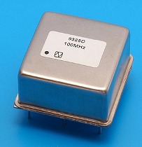
9325D(Fixed Communication)/Oven-Controlled Crystal Oscillator (OCXO)/NDK
The unit price of this OCXO is approximately 1,100 USD!
Last edited:
Bunpei,
Is the specs good for the 5920A-AQJ70(Fixed Communication)/Temperature Compensated Crystal Oscillator (TCXO)/NDK ??
what is your opinion on the Zegar wersja MK II hybryd ?
Is the specs good for the 5920A-AQJ70(Fixed Communication)/Temperature Compensated Crystal Oscillator (TCXO)/NDK ??
what is your opinion on the Zegar wersja MK II hybryd ?
...
Is the specs good for the 5920A-AQJ70(Fixed Communication)/Temperature Compensated Crystal Oscillator (TCXO)/NDK ??
what is your opinion on the Zegar wersja MK II hybryd ?
As I have no experience on the oscillator board at all, I have no comment on it. I'm not sure whether the NDK oscillator used on the board is the TCXO or not.
However, in general, you would find a certain degree of improvements when you use so-called "low jitter" oscillators. I think qualities of NDK oscillators are always good enough in my limited experiences.
Bunpei
The
Digital engineers whom I trust have told me that phase noise (especially phase noise at low frequencies) is the important spec for an audio clock.
My understanding is that TCXO, and OCXO excel in terms of very long term stability, but this is not what matters for audio, same as with so called atomic clocks. Long term stability is great if one needs a clock reference which will not vary over years, but this does not help audio performance.
I believe Bunpei has shown the phase noise plots for some NDK oscillators which looked pretty good. If you are searching for an oscillator module for audio use, look for something with low phase noise. If the manufacturer does not publish phase noise specs, it is probably safe to assume that they are not very good. Here in the US, of the oscillators which are actually obtainable in the relevant frequencies, the Crystek CCHD series parts are designed for audio, and have decent phase noise specs: much better than the typical parts used in most commercial products.
Excellent results using an SAW oscillator 125Mhz to clock ESS9018! So far the best results I got in my quite many experiments (over)clocking ESS9018.
I had to precise (one more time) that my experiments were made on the DAC stage of BDP95 Oppo player. I do not know details about the firmware used to control the DAC chip, and/or its software setup. As it is the firmware in this case, ESS9018 it works excellent clocked at 125Mhz (using this SAW type oscillator).
Still be a mystery for me why ESS9018 work better (perceptual) and can actually work with excellent results at higher clock frequencies than the designer him self recommend as max in the chip data sheet.
Nice to hear from others about their results (experiences) in (non standard) clocking of ESS9018.
Last edited:
Were your tests done using the BDP95 I/V-stage and balanced output?I had to precise (one more time) that my experiments were made on the DAC stage of BDP95 Oppo player.
Were your tests done using the BDP95 I/V-stage and balanced output?
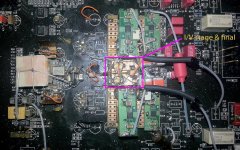
I`ve used only the SE output so far. No, I did not used the original stages of BDP 95. I did not trusted/liked at all the original Oppo design of I/V & final stages. I build it my own I/V stage and output (as is to be seen in the picture). My output stage is used for moment as SE, but is connected already for use it as balanced. My balanced amplifier is not ready to work yet...
If somebody will be willing to try an 125 Mhz oscillator with the use of the original Oppo design for I/V & final stage, it will be very interesting to hear about the results...
Last edited:
I always see cheap computer mb equipped with this ESS logo sound chip, but this 9018 is very expensive.
I personally doubt about PC motherboards designed to use ESS DACs for audio. But who knows... The chip is very high tech and is worth to pay that price for it (in my opinion).
I`ve used only the SE output so far. No, I did not used the original stages of BDP 95. I did not trusted/liked at all the original Oppo design of I/V & final stages. I build it my own I/V stage and output (as is to be seen in the picture). My output stage is used for moment as SE, but is connected already for use it as balanced. My balanced amplifier is not ready to work yet...
If somebody will be willing to try an 125 Mhz oscillator with the use of the original Oppo design for I/V & final stage, it will be very interesting to hear about the results...
Forgot the picture...
Attachments
I have an OCXO of 100 MHz sine wave output at my hand. If you want to evaluate it, I can send it to you.
The model is 9325D(Fixed Communication)/Oven-Controlled Crystal Oscillator (OCXO)/NDK
Its list price is approximately 1,000 Euro. Phase noise measurement chart for the individual device is available.
As the output is sine wave of +-0.9 V(1.8 V p-p) amplitude, I applied an adjustable DC bias using batteries and fed the biased sine output directly to XI pin of ES9018. The idea of the direct input was given by Dustin.
You need +12V power for the device.
I felt the sonic result of this OCXO was definitely better than the standard Crystek oscillator used on Buffalo II. However, the cost performance was not so high enough. After I once knew the superior performance of synchronous master clocking scheme, I decommissioned it.
Cost of 2 pieces + shipping to Rome Italy ?
Is there a 14 DIP version ?
Excellent results using an SAW oscillator 125Mhz to clock ESS9018! So far the best results I got in my quite many experiments (over)clocking ESS9018.
I had to precise (one more time) that my experiments were made on the DAC stage of BDP95 Oppo player. I do not know details about the firmware used to control the DAC chip, and/or its software setup. As it is the firmware in this case, ESS9018 it works excellent clocked at 125Mhz (using this SAW type oscillator).
Still be a mystery for me why ESS9018 work better (perceptual) and can actually work with excellent results at higher clock frequencies than the designer him self recommend as max in the chip data sheet.
Nice to hear from others about their results (experiences) in (non standard) clocking of ESS9018.
Where you have buy it ?
Cost of 2 pieces + shipping to Rome Italy ?
Is there a 14 DIP version ?
Approximately 2,000 EURO. No 14 DIP version is available.
- Home
- Source & Line
- Digital Line Level
- ESS9018 - try new, try more...