As jcarr said, the vertical axis of the graph is the "phase angle" (theta, θ)
between voltage and current. You can measure the value easily using a LCR meter.
A group of advanced audiophiles in my hometown region is recently establishing such an empirical rule that "a capacitor that has a good phase vs. frequency plot yields a good sonic effect both on decoupling and coupling purposes in terms of unclouded sound."
In this context, "a good phase plot" means;
1. Fluctuation of phase value is small
2. No large phase value change appears in audio frequency range
Even if you feel anything doubtful on my report, I will not ram the capacitor or the empirical rule into your throat.(The capacitor is too large to swallow down, actually.) You have your thoughts and your ways.
I have one thing to make it clear. I have not removed any capacitors originally on board on the Buffalo II main board. A set of ceramic capacitors remains there.
As jcarr said, the vertical axis of the graph is the "phase angle" (theta, θ)
between voltage and current. You can measure the value easily using a LCR meter.
A group of advanced audiophiles in my hometown region is recently establishing such an empirical rule that "a capacitor that has a good phase vs. frequency plot yields a good sonic effect both on decoupling and coupling purposes in terms of unclouded sound."
In this context, "a good phase plot" means;
1. Fluctuation of phase value is small
2. No large phase value change appears in audio frequency range
Even if you feel anything doubtful on my report, I will not ram the capacitor or the empirical rule into your throat.(The capacitor is too large to swallow down, actually.) You have your thoughts and your ways.
I have one thing to make it clear. I have not removed any capacitors originally on board on the Buffalo II main board. A set of ceramic capacitors remains there.
I do not doubt your report and I do not feel like so... I`m just thinking and trying to find out why so an so... Explanations... That`s all.
By the way, thanks for your explanations.
Bunpei, if I have offended you, I apologise.
Maybe I was too harsh in my comments. Having been in the electronic industry for many years and now being in the academic "world" have made me a bit skeptical when I see such a flat line among other "normal" curves.
Best regards,
S.
Maybe I was too harsh in my comments. Having been in the electronic industry for many years and now being in the academic "world" have made me a bit skeptical when I see such a flat line among other "normal" curves.
Best regards,
S.
As jcarr said, the vertical axis of the graph is the "phase angle" (theta, θ)
between voltage and current. You can measure the value easily using a LCR meter.
A group of advanced audiophiles in my hometown region is recently establishing such an empirical rule that "a capacitor that has a good phase vs. frequency plot yields a good sonic effect both on decoupling and coupling purposes in terms of unclouded sound."
In this context, "a good phase plot" means;
1. Fluctuation of phase value is small
2. No large phase value change appears in audio frequency range
Even if you feel anything doubtful on my report, I will not ram the capacitor or the empirical rule into your throat.(The capacitor is too large to swallow down, actually.) You have your thoughts and your ways.
I have one thing to make it clear. I have not removed any capacitors originally on board on the Buffalo II main board. A set of ceramic capacitors remains there.
Dear Coris and staccatiss,
Please do not be worry so much. I don't mind.
Even if the effect of the capacitors are out of your orthodox theory, I'd like to recommend you try those.
By the way, as staccatiss reported his comment on TPA transformer I/V thread, I think synchronous MCLK feed is very effective either.
Coris, why don't you try that method in your system?
Dear Coris and staccatiss,
Please do not be worry so much. I don't mind.
Even if the effect of the capacitors are out of your orthodox theory, I'd like to recommend you try those.
By the way, as staccatiss reported his comment on TPA transformer I/V thread, I think synchronous MCLK feed is very effective either.
Coris, why don't you try that method in your system?
Hi Bunpei
You know, I didn`t succeed yet to put together my Buffalo system... so, that because I didn`t tried yet the synchronous clock. My actually system do not permit me this, or all is too complicated. I will try it... as soon as I would have the possibility.
I have tried a collective set of ceramic capacitors ( 100 microF x 10 ) at last.
Its sonic impression I felt was "clear". However, among Sanyo OS-CON, Panasonic electrolytic capacitor, a collective set of Tantalum capacitors, CDE film capacitor and a collective set of ceramic capacitors, I like the giant film capacitor manufactured by Cornell Dubilier Electronics best. (Naturally, each type has each characteristic.)
Its sonic impression I felt was "clear". However, among Sanyo OS-CON, Panasonic electrolytic capacitor, a collective set of Tantalum capacitors, CDE film capacitor and a collective set of ceramic capacitors, I like the giant film capacitor manufactured by Cornell Dubilier Electronics best. (Naturally, each type has each characteristic.)
I have tried a collective set of ceramic capacitors ( 100 microF x 10 ) at last.
Its sonic impression I felt was "clear". However, among Sanyo OS-CON, Panasonic electrolytic capacitor, a collective set of Tantalum capacitors, CDE film capacitor and a collective set of ceramic capacitors, I like the giant film capacitor manufactured by Cornell Dubilier Electronics best. (Naturally, each type has each characteristic.)
Thanks for your feedback! Good to know that are different sonic results in this case.
In the last time I found out about something interesting... Is about I/V & final stage (stereo) for ESS9018. I will search a little bit more before publish something.
Do you use in your system TPA I/V & final stage, or something else? For moment I use/run my own one...
Last edited:
Please shareDo you use in your system TPA I/V & final stage, or something else? For moment I use/run my own one...
... Do you use in your system TPA I/V & final stage, or something else? ...
As I favor a minimalist approach, I use no I/V stage. My way of monitoring is connecting a tweaked Etymotic Research ER-4S earphones to a balanced analog output of Buffalo II or Buffalo III board. Each earphone drivers is said to have 5 ohm impedance and a variable resister is inserted in serial. I believe no visible coupling capacitors are in the signal path. Therefore, I think I can monitor a raw characteristic of the DAC chip. (One exception is possible effects of the variable resister.)
(One exception is possible effects of the variable resister.)
...and a highly inductive/reactive load (headphone coils).
As I favor a minimalist approach, I use no I/V stage. My way of monitoring is connecting a tweaked Etymotic Research ER-4S earphones to a balanced analog output of Buffalo II or Buffalo III board. Each earphone drivers is said to have 5 ohm impedance and a variable resister is inserted in serial. I believe no visible coupling capacitors are in the signal path. Therefore, I think I can monitor a raw characteristic of the DAC chip. (One exception is possible effects of the variable resister.)
It had happened that you`ve scoped the output of your configuration? I`m interested (for comparing reasons) in how can look like a plot of the final output of the ESS9018 system, noise point of view, or what can be there without main signal (sound)...
Last edited:
I think to show you something interesting. Maybe somebody else is already known with those things. For me was just a surprise.
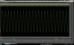
I`ve created an 80kHz wav file with Auditon - Tone generator. You can see here the print screen of this file. I really do not know how it can looks like in real the created signal. I take as true what Audition shows about that signal in the file...
80Khz is of course no any "tone", but the software it works fine to generate like this (up to 95kHz as tested). The file is mono, 192Khz sampling and 24bit (created 32 bit and wav finally coded as 24 bit, -3dB)
I`ve copied this file on an USB stick and stack it in to my Oppo95 (which I use for moment as platform for my ESS9018 experiments).
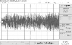
On the RCA output I have this what is to see it here...
Just exactly wave I`ve software generated! Just 2-4 times the audio frequency spectre! No any distortion! Just fine, clean sinus!
My scope is a digital one, so the captured picture looks like it looks (digital steps/stair). Anyway, the sinus is just very clean...
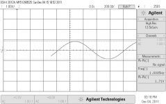
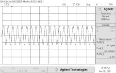
For comparation I show her too, a captured screen from one channel of stereo playing a normal audio file (very dynamic orchestra, 44,1 Khz).
I`ve tested too with 40kHz "tone" signal (actually this was the first test...), and then with 1Hz one (the same samplings and the rest...). As you can notice, is the output pp level which is diffrent on those tests. The level decrease, but the sinus is just perfect.
I have the option for creating also square waves, but this sotware does not succed to create something like this very well. Is a kind of square wave, and looks very bead at such frequencies (it looks fine in audio normal spectre). Anyway, those square created files I`ve plaied out on ESS9018 stage looks exactly like the original generated "sound".
My ESS9018 is running now on 122,88Mhz clock, and I have no any filter between I/V and final stage. Final stage is supplyied with +/-15v, I/V stage with +/-13v
I think that is just amazing that ESS98018 can convert ("play") such frequencies without any problem. I think that is also amazing that such siganls can goes through all the before stages and after all conversions it come out without any distortion...
I`ve tested with FLAC coded files in the same conditions. The same results...
Waiting for your comments...
I`ve created an 80kHz wav file with Auditon - Tone generator. You can see here the print screen of this file. I really do not know how it can looks like in real the created signal. I take as true what Audition shows about that signal in the file...
80Khz is of course no any "tone", but the software it works fine to generate like this (up to 95kHz as tested). The file is mono, 192Khz sampling and 24bit (created 32 bit and wav finally coded as 24 bit, -3dB)
I`ve copied this file on an USB stick and stack it in to my Oppo95 (which I use for moment as platform for my ESS9018 experiments).
On the RCA output I have this what is to see it here...
Just exactly wave I`ve software generated! Just 2-4 times the audio frequency spectre! No any distortion! Just fine, clean sinus!
My scope is a digital one, so the captured picture looks like it looks (digital steps/stair). Anyway, the sinus is just very clean...
For comparation I show her too, a captured screen from one channel of stereo playing a normal audio file (very dynamic orchestra, 44,1 Khz).
I`ve tested too with 40kHz "tone" signal (actually this was the first test...), and then with 1Hz one (the same samplings and the rest...). As you can notice, is the output pp level which is diffrent on those tests. The level decrease, but the sinus is just perfect.
I have the option for creating also square waves, but this sotware does not succed to create something like this very well. Is a kind of square wave, and looks very bead at such frequencies (it looks fine in audio normal spectre). Anyway, those square created files I`ve plaied out on ESS9018 stage looks exactly like the original generated "sound".
My ESS9018 is running now on 122,88Mhz clock, and I have no any filter between I/V and final stage. Final stage is supplyied with +/-15v, I/V stage with +/-13v
I think that is just amazing that ESS98018 can convert ("play") such frequencies without any problem. I think that is also amazing that such siganls can goes through all the before stages and after all conversions it come out without any distortion...
I`ve tested with FLAC coded files in the same conditions. The same results...
Waiting for your comments...
Attachments
Last edited:
... I think that is just amazing that ESS98018 can convert ("play") such frequencies without any problem. ...
I had once observed sweep sine signal of 100 kHz - 176.4 kHz using SDTrans384 and ES9018 on oversampling mode. (The source was 352.8kHz/24 bit PCM) Your result is not surprising. Just before aliasing noises appeared in the near 176.4 kHz region, the output kept a clean sine wave.
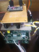
By the way, my final configuration tested for my co-worker is like this;
1. Doubly stacked Buffalo III
(Not dual mono. Paralleled stereo mode)
2. Synchronous master clock feed of 22.5792 or 24.576 MHz from SDTrans384
(By using a non-oversampling filter mode, sources with sampling frequencies up to 384 kHz can be played without noises.)
3. Linear regulator sub boards for AVCC(+3.3V), VCC(+1.2V), DVCC(+3.3V)
At each input side of a linear regulator for AVCC, a film capacitor of CDE 100 microF/800V and OS-CON of Sanyo 10 microF/15V are attached.
At each output side for AVCC, Copper foil PPS(Poly-phenylene-sulfide) film capacitor of Sunring 0.022 microF/250V
(No big capacitors are attached.)
Attachments
Bunpei, interesting your experience with 170Khz on ESS9018... I was enough surprised to see 80Khz...")
May I ask how you`ve generated that PCM file?
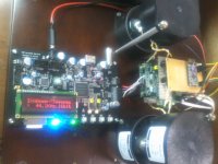
I`ve seen today that the picture in my first post (about 133,3Mhz clock on ESS9018) pass now over 1200 hits/views... It seems there were enough many who were interest to see that oscillator coupled to the DAC chip... I have to say, that the picture by it self is not so exciting.... Is more exciting to solder together those components and hear the system how it sounds....
I think is quite strange that from those so many people interested in this case, was nobody yet who reproduced in fact this experiment and come with some impressions about... But anyway, this is not so important...
In the last time I did some detail improvements in my system, and I thought to go again through different clocks for ESS9018, to refresh my conclusions about this aspect.
I`ve tried again with 133,3Mhz clock after a period I`ve used an 122,8Mhz oscillator for the DAC.
I`ve wrote in a earlier post that I`ve detected some very low level sparkling noises in using this clock for ESS9018 (in the quiet passages of the playback). Now I know now that this it was because another small details in my system, which are now fixed.
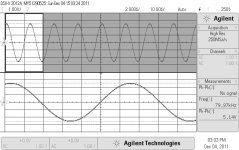
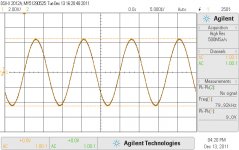
ESS9018 it works very well with such high clock frequency! I`ve took a picture (attached here) of my 80Khz "sound" file played back with this clock in place.
The sound is very detailed and the bass is very impressive too. Very hard to hear the lowest bass sound, but can feel it very well and quite strong in the body. This at an output power of no more than 2-3W...
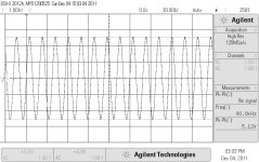
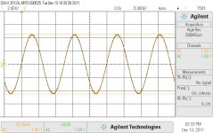
I`ve then mounted again the Crystek 100Mhz clock and tested in the same conditions. The picture take it is to be seen here. Just identical with that using 133,3Mhz clock...
The sound impression is very good also with this 100Mhz clock. Very little difference in the 133,3Mhz clock favour.
In the last I`ve got an 112,896Mhz oscillator. Unfortunately is not a very high performance oscillator, and more is an VXO... I just couldn`t find a better one at this frequency. Sceptic enough I`ve soldered in place and fired up the system.
This was the winner! But the pictured signal still be identical with the another ones... The diffrence is not to be seen on the scope display...
The diffrence between those oscillators coupled to ESS9018 (as I experienced) it was only in the depth of sound stage. With this clock frequency (112,896Mhz) I`ve got the bigest expansion in backward and in close presence of the sounds in sound stage. The wide of the sound stage is still be the same with all those clocks, but the expansion is in back/far, close/near using an 112,896Mhz clock. Why? I really don`t know... Maybe some (another) specialists can find an explanation...
It can depend from system to system, but I experiened like this in mine. BTW, I use for the moment single ended output...
In the end a little question: what about (local) shielding in such audio systems? Give it a try...
May I ask how you`ve generated that PCM file?
I`ve seen today that the picture in my first post (about 133,3Mhz clock on ESS9018) pass now over 1200 hits/views... It seems there were enough many who were interest to see that oscillator coupled to the DAC chip... I have to say, that the picture by it self is not so exciting.... Is more exciting to solder together those components and hear the system how it sounds....
I think is quite strange that from those so many people interested in this case, was nobody yet who reproduced in fact this experiment and come with some impressions about... But anyway, this is not so important...
In the last time I did some detail improvements in my system, and I thought to go again through different clocks for ESS9018, to refresh my conclusions about this aspect.
I`ve tried again with 133,3Mhz clock after a period I`ve used an 122,8Mhz oscillator for the DAC.
I`ve wrote in a earlier post that I`ve detected some very low level sparkling noises in using this clock for ESS9018 (in the quiet passages of the playback). Now I know now that this it was because another small details in my system, which are now fixed.
ESS9018 it works very well with such high clock frequency! I`ve took a picture (attached here) of my 80Khz "sound" file played back with this clock in place.
The sound is very detailed and the bass is very impressive too. Very hard to hear the lowest bass sound, but can feel it very well and quite strong in the body. This at an output power of no more than 2-3W...
I`ve then mounted again the Crystek 100Mhz clock and tested in the same conditions. The picture take it is to be seen here. Just identical with that using 133,3Mhz clock...
The sound impression is very good also with this 100Mhz clock. Very little difference in the 133,3Mhz clock favour.
In the last I`ve got an 112,896Mhz oscillator. Unfortunately is not a very high performance oscillator, and more is an VXO... I just couldn`t find a better one at this frequency. Sceptic enough I`ve soldered in place and fired up the system.
This was the winner! But the pictured signal still be identical with the another ones... The diffrence is not to be seen on the scope display...
The diffrence between those oscillators coupled to ESS9018 (as I experienced) it was only in the depth of sound stage. With this clock frequency (112,896Mhz) I`ve got the bigest expansion in backward and in close presence of the sounds in sound stage. The wide of the sound stage is still be the same with all those clocks, but the expansion is in back/far, close/near using an 112,896Mhz clock. Why? I really don`t know... Maybe some (another) specialists can find an explanation...
It can depend from system to system, but I experiened like this in mine. BTW, I use for the moment single ended output...
In the end a little question: what about (local) shielding in such audio systems? Give it a try...
Attachments

Last edited:
... The wide of the sound stage is still be the same with all those clocks, but the expansion is in back/far, close/near using an 112,896Mhz clock. Why? I really don`t know... Maybe some (another) specialists can find an explanation...
For me, the reason is simple. 112.896 MHz = 256 x 10 x 44.1 kHz.
(I assume you played 44.1 kHz series sampling rate sources).
Why don't you try a synchronous master clock feed to your ES9018 chip?
(I think it's better for you to describe your experiment conditions on your posting.)
Last edited:
For me, the reason is simple. 112.896 MHz = 256 x 10 x 44.1 kHz.
(I assume you played 44.1 kHz series sampling rate sources).
Why don't you try a synchronous master clock feed to your ES9018 chip?
(I think it's better for you to describe your experiment conditions on your posting.)
Yes, that because I`ve tried this frequency. Because have something to do with 44,1Khz sampling...
The problem is that I use this clock to play everything and I have the same result: expanded sound stage more than with the other oscillators. Even in DSD field... The another oscillator (122,88Mhz) was good for 48Khz range, but is more sound stage with this 112Mhz... even when play 48-192Khz sampling. Strange enough... You know, the master clock in this system I use for the moment is quite far away from this DAC chip. I think is not quite well to have a long wire (approx 15cm) in between those chips for an 25Mhz frequency... Do you think can be OK enough to transport the master clock through so long distance to feed the DAC with? To extract it from I2S become to complicated in this configuration I use for the moment...
I do hope that one day (near future) I will succeed to fire up my Buffalo. So, then will be quite much to experiment with that...
As I wrote in previus posts, I use for the moment ESS9018 only in stereo mode. Have no access to the firmvare and registry in this system, and I do not want to spend more time to find out about this field on this platform. I just want to bring it up at an enough high level end be finish with it. Is quite difficult to mod this system... Now I have the DAC decoupled with 1000µ on both digital and analogue (ceramic and film SMD). The same in I/V & final stages. I/V and final stage without any capacitor involved in the signal path, and I can have an approx 25v (pp) swing at the output RCA (LM6172 final).
Last edited:
... I think is not quite well to have a long wire (approx 15cm) in between those chips for an 25Mhz frequency... Do you think can be OK enough to transport the master clock through so long distance to feed the DAC with? ...
Why don't you try it first? If you obtain a good sound, you can be happy!
Even if you get any wrong result, you can consider alternative ways in the next step, for example, using a coaxial cable and tuning a termination resister or inserting a buffer.
In my case, I tried a various kind of bypass capacitors for AVCC power lines based on your report and suggestions and came to find the best ones for me.
OK, I will try... You right! Of course is about a coaxial cable to be used anyway... I actually have that good coaxial cable...
Last edited:
- Home
- Source & Line
- Digital Line Level
- ESS9018 - try new, try more...