Where you have buy it ?
Farnell. In an earlier post Joe mentioned the part number too...
Hi folks (and Joe Rasmussen)!
I think to "pay back" to Joe for his advice to use an SAW oscillator to clock ESS9018. The 125Mhz SAW oscillate like a charm and the beautiful sound is coming out of Sabre chip...
But Joe and others, you may try to battery power the oscillator for ESS9018...
Is quite simple and the result is... not dramatic, but more subtle... Is like one switch the TV signal from standard to HD (on an HD display). So, more details (in the shadows...") ) in the sound stage, more nuances, more definition in the resulting sound.
) in the sound stage, more nuances, more definition in the resulting sound.
I`ve used a mobile phone battery, 1,6A/h. I had this at the moment, but it works for sure everything else (3,7v). Of course is not way to be used an regulator after this battery. The delivered current per hour is so large comparing to the needs of the oscillator (30mA), that will not be problem to loose the power for the clock. When is to turn off the "machine", then the battery will be charged again. I do not know yet how will react the oscillator to the discharging tension variation. The oscillator is specified to work in parameters for +/-0,3v power variation. This mean something between 3,6 - 3,0v. The battery deliver 3,8v soon after is charged, so one may lower the tension for the oscillator to the max safe specified (3,6v). An resistor will do this. I think will be not any problem with this variation, but I will observe what is happen with the oscillator while the battery is discharging...
So, try it! Carefully calculate to assure the right tension and the needed current for the oscillator you have from a Li-Ion battery. A relay will connect and disconnect the power accordingly for the oscillator when power ON in your system set up. When turning the unit off then the battery may be charged from a dedicated and good enough quality charger (protected and power off when the battery is finish charged).
The connections from battery to the oscillator may be the shorty as possible, to not collect noises through the long wires. As the battery have a quite big surface, I think is better to be shielded it too.
I think to "pay back" to Joe for his advice to use an SAW oscillator to clock ESS9018. The 125Mhz SAW oscillate like a charm and the beautiful sound is coming out of Sabre chip...
But Joe and others, you may try to battery power the oscillator for ESS9018...
Is quite simple and the result is... not dramatic, but more subtle... Is like one switch the TV signal from standard to HD (on an HD display). So, more details (in the shadows...
) in the sound stage, more nuances, more definition in the resulting sound.I`ve used a mobile phone battery, 1,6A/h. I had this at the moment, but it works for sure everything else (3,7v). Of course is not way to be used an regulator after this battery. The delivered current per hour is so large comparing to the needs of the oscillator (30mA), that will not be problem to loose the power for the clock. When is to turn off the "machine", then the battery will be charged again. I do not know yet how will react the oscillator to the discharging tension variation. The oscillator is specified to work in parameters for +/-0,3v power variation. This mean something between 3,6 - 3,0v. The battery deliver 3,8v soon after is charged, so one may lower the tension for the oscillator to the max safe specified (3,6v). An resistor will do this. I think will be not any problem with this variation, but I will observe what is happen with the oscillator while the battery is discharging...
So, try it! Carefully calculate to assure the right tension and the needed current for the oscillator you have from a Li-Ion battery. A relay will connect and disconnect the power accordingly for the oscillator when power ON in your system set up. When turning the unit off then the battery may be charged from a dedicated and good enough quality charger (protected and power off when the battery is finish charged).
The connections from battery to the oscillator may be the shorty as possible, to not collect noises through the long wires. As the battery have a quite big surface, I think is better to be shielded it too.
Last edited:
Forgot something important for they who want to experiment or use battery powered oscillator. Just in case, use an pico fuse inserted between the battery and the oscillator. Something accordingly with the needed current flowing in the circuit.
I experienced earlier a defective oscillator which after a while it get shorted to GND on the power pin. Then it were the regulator which switched into protection. When about battery with few amp/h it could be quite dangerous to be shorted to GND by a defective component.
So, please use a fuse when is to power something from battery!
Well, it depends... When about such power sources as batteries it is a must, because is the only protection. Where regulators are involved, one may appreciate where is to be used a fuse... A fuse after a regulator as a power source is a little bit stupid, I can say. The most (chip or not) regulators are (may be) protected by design... A fuse before regulators it may make more sense (if important currents are involved).
Anyway, one may appreciate the right place for such protection. But more discussions in this thread about "fuse theory" it may come out of topic, I suppose...
In this particular
Anyway, one may appreciate the right place for such protection. But more discussions in this thread about "fuse theory" it may come out of topic, I suppose...
In this particular
A fuse after a regulator as a power source is a little bit stupid
Of course it is (typically). I don't think I said to do that... I said always use a fuse.
In this power setup for the clock oscillator for ESS9018, is quite natural at one may feel the need to monitor or measure the battery tension, discharge rate an so on.
I only want to express my opinion here that any connection to the power pin of the oscillator with long wires/connection or having connected an monitor device, will not be fortunate at all. Will of course not destroy something but will just induce noises into the system. If is to measure or monitor the battery status, then this may be done when the device is off, and the battery is switched out from the oscillator circuit.
Most reasonable sequence I think is to monitor the battery when device is off, measure by this monitor device/circuit the tension of the battery, and then decide and connect the charger to charge it. To realize a such monitor circuit it may not be very complicated (I will try it later), and the battery for sure it will "feel" better to be charged this way than every time the main device is off...
After I`ve used more than 6 hours my fully charged 1,6A/h battery, to run the oscillator, its tension level drops with approx 40mV... Is plenty of energy there for such use.
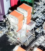
Improved design for the idea in first picture of this thread...
2x4000µF tantal decoupling on L/R AVCC (3,8V) of ESS9018. No different local regulators, but one low noise for both analogue rails of the chip.
2x4000µF tantal decoupling on L/R AVCC (3,8V) of ESS9018. No different local regulators, but one low noise for both analogue rails of the chip.
Attachments
Last edited:
funny, the aim seems to be to be close to the chip and the point of SMD parts is to have low inductance, but the leads to connect the chip are longer than what is possible just using leaded caps next to the dac ...
The effect of 4000uF pr. channel on the AVCC are most possibly much more important than the tiny inductance caused by the 4 - 5 millimeters of wire - the original decoupling close to the chip are still in action..
I expect this "modification" improves the fidelity greatly as the AVCC also are the DAC reference and now the -3dB point of decoupling are moved several decades down in frequency...
expect all you want, give it a decent reg and the 4000uf is completely meaningless, but it sure looks 'pretty'...The effect of 4000uF pr. channel on the AVCC are most possibly much more important than the tiny inductance caused by the 4 - 5 millimeters of wire - the original decoupling close to the chip are still in action..
I expect this "modification" improves the fidelity greatly as the AVCC also are the DAC reference and now the -3dB point of decoupling are moved several decades down in frequency...
You completely missed the point, the point was that here we have SMD caps that are designed this way to be compact and low inductance, because they have no leads ... but the way they are used here means the leads added to them are longer and more inductive than if a 4000uf leaded cap were placed optimally with trimmed leads. (if indeed a 4000uf cap here could be called optimal under any circumstance, but lets pretend it can be...)
there is no point using SMD caps if you are going to add leads to them. those tantalums wont be terribly cheap either and you are paying for attributes that are wasted in this format.
there are better ways to get the noise down, a simple passive composite filter with much less capacitance would do better.
Last edited:
How?The effect of 4000uF pr. channel on the AVCC are most possibly much more important than the tiny inductance caused by the 4 - 5 millimeters of wire - the original decoupling close to the chip are still in action..
To do what?I expect this "modification" improves the fidelity greatly as the AVCC also are the DAC reference and now the -3dB point of decoupling are moved several decades down in frequency...
It is true that the clue with the SMD ceramic caps in my first picture/try placed so near to the chip as possible, it were to lower too ESI as much as possible. Of course it is not possible to connect those caps without having some wires in between to the chip pins. The problem with the ceramic caps is that their capacity is temperature dependent. The capacity get lower when the temperature rise. The DAC chip it not run completely cold. So...
Using tantalum big capacities, one get rid of the temperature problems, when placing those right on the chip (shortest connection possibility, when the PCB is already designed for another decoupling solutions). One advantage more using those caps is that one can have bigger capacity for the used place, than it may have using ceramics.
One such tantalum cap have an ESR of 0,08 ohm. So totally is there 0,002 ohm ESR per total 4000µF capacity. Those caps are specially designed for the lowest possible ESI. The wires introduce an ESI value, but for all the system that is extremely low (when is almost nothing for the caps it self).
I strongly suggest to all of those who critic the method, to try yourself (DIY), register the results, and then come with critics...
Sorry qusp, but using filters in the audio signal path it seems to me just stupid. No matter how good are those filters, or how perfect designed it is that filter, they affect the useful signal quite much. About this I'm just convinced now.
The big decoupling capacities is a good solution, with very good results. Try it!
It is true that this method improve the quality of the outputted audio much. It is about increasing in dynamics and the quality in the lower end of the audio spectre. The bass definition is very impressive. But what for I may try to preach this method more? Only apply it (if not just like in the picture, then find another way), and you will hear the difference...
PS. Please note that the AVCC pins of the chip are lifted up (unsoldered from their tabs) and connect directly to the caps and further to the power. The GND of the system it still be intact, connected to the board. The caps are independent for L/R connections to the chip.
I may recognize that the connexions pins - caps it could be even shorter, and the wires should be routed other/better ways. I have done not very well there, but I will remember next time...
Last edited:
Coris, erm... just what do you think your cap is? its not a filter? you do realize i'm talking about a filter on the AVCC regulator yes? you think there are not lumped R, L, C elements in there already and you have just put a cap there? you think adding small parallel caps to the larger caps after lifting the pin means the smaller cap will actually do something? you think that mΩ impedance means something here when its some cm away? wow... youre just making your rhetoric up as you go along...
and I cannot help you either Ray, if after twice explaining the same thing very simply you still dont understand... you somehow think that just throwing the largest cap you can at the problem is useful when you can make a better filter... if your regs need caps like this to make low enough noise, then you have issues. you think there is only differential effects here? you think installing a contraption on top of the dac, stacking caps upwards makes the path short?
you didnt see he had done this? meaning the local decoupling has been taken out of play and the stack of low impedance caps connect to AVCC through a wire and are grounded through a wire, the current path is very long and now where is the IV stage return connecting? given unbroken direct low Z connection from the IV stage is recommended and the AVCC pins are lifted... I wonder how well the regulators like feeding a 4000uf inrush...
not an improvement... but I forgot how hyper intelligent you are Ray... you knew that all along, just playing right?Coris said:PS. Please note that the AVCC pins of the chip are lifted up (unsoldered from their tabs) and connect directly to the caps and further to the power.
Last edited:
yeah i've mentioned that here before, he doesnt believe his sculptures attract noise and doesnt believe the faster clocks increase noise either. then hes got some crazy amount of gain on the IV stage, to 'increase DNR' all this despite the conglomerate only being fairly tenuously connected to ground through a wire (a shiny wire) when there is a perfectly good ground plane
- Home
- Source & Line
- Digital Line Level
- ESS9018 - try new, try more...