The NDK which TAD is using-do you know if that is a custom part, or is there a series available from them with that level of performance, and if so, can they be purchased in single unit quantities somewhere?
I heard that the device was a custom part co-developed by TAD and NDK. I have never found it on NDK's product listing published on their web site.
Moreover, the low phase noise profile must be achieved by its associated power supply module. The black box left to the main player box is a dedicated power supply unit.
An externally hosted image should be here but it was not working when we last tested it.
By the way Bunpei, what is your power supply solution in your DAC system at this moment? I mean the main power supply.
Thanks.
Last edited:
... what is your power supply solution in your DAC system at this moment? I mean the main power supply. ...
My power supplies are very humble and simple as shown on this photo,
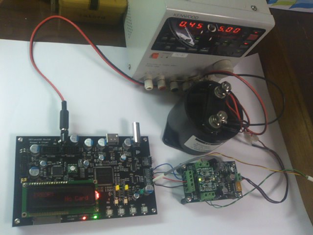
but suitable for various experiments including Class-D amplifiers.
1. +-18V, +8V, -6V Kenwood regulated DC Power Supply with
CDE(Cornell Dubilier Electronics, Inc.) 100uF 600V Film capacitor
(The power supply itself is not for audio grade. However, the CDE Film capacitor makes it of audio grade.)
2. Panasonic "Evolta" Alkaline Batteries
(This is not rechargeable.)
The best power supply unit that I assembled for my friend recently was;
- Transformer: Feastrex "Finemet" core type, order made
- Rectifier: Cree Inc., Zero Recovery type
- Linear regulator: Fairchild microA723 compatible chip with Toshiba Power FET
- Choke coil: Feastrex "Finemet" core type, order made
- Capacitor: CDE 100uF 600V film capacitor
But anyway... I look forward to "hear" about your new experiments with different decoupling ways, caps types, and so on...
I tried collective tantalum chip capacitors at the output side and my friend did Panasonic FC electrolytic capacitor. We think each capacitor showed its own characteristic on their sonic impression and the both results are not negative at all. One collective tantalum capacitor consists ten 100 microF chips, totally 1,000 microF / side.
In the next step, we will try CDE film capacitors and collective ceramic chip capacitors.
Nice to have your confirmation about this.
Yes, is right that is a different result (sound) using different types decoupling caps. Is also difference when using the same type caps in different stages. I prefer the tantalum decoupling in final and ceramics in the I/V stage for example... One have to try different configuration to find the best results... I did not noticed a special result with film caps as decoupling. They can be quite big for large capacities I suppose... But good to hear from you about your results.
In the next step, we will try CDE film capacitors and collective ceramic chip capacitors.
First, I really want to express my true gratitude to Coris.
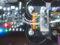
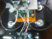
For bypass capacitors on AVCC power line of ES9018 (Buffalo II), I tried 100 microF 800V film capacitor (944U101K801) manufactured by Cornell Dubilier Electronics (CDE) at the output side of my DIY linear regulator sub board.
(The big "oil tanks" in the attached pictures are CDE film capacitors. Only two of four in the picture are actually connected.)
The result of sonic improvements are astonishing.
I felt better in all aspects of its sonic characteristics.
At the same time, I realized a great potentiality of this DAC chip as well as that of TPA Buffalo II board.
I do not believe ordinary audiophiles will not try the same use of the capacitor. However, I am simply satisfied with this personal experience in my experimental environment. "Music is wonderful!"
Thank you, Coris, Russ & Brian and Dustin! Thank you, Chiaki!
Attachments
I do not believe ordinary audiophiles will not try the same use of the capacitor.
I'm sorry. I made a grammatical error in the previous post. The correct statement is;
"I do not believe ordinary audiophiles will try the ..."
First, I really want to express my true gratitude to Coris.
For bypass capacitors on AVCC power line of ES9018 (Buffalo II), I tried 100 microF 800V film capacitor (944U101K801) manufactured by Cornell Dubilier Electronics (CDE) at the output side of my DIY linear regulator sub board.
(The big "oil tanks" in the attached pictures are CDE film capacitors. Only two of four in the picture are actually connected.)
The result of sonic improvements are astonishing.
I felt better in all aspects of its sonic characteristics.
At the same time, I realized a great potentiality of this DAC chip as well as that of TPA Buffalo II board.
I do not believe ordinary audiophiles will not try the same use of the capacitor. However, I am simply satisfied with this personal experience in my experimental environment. "Music is wonderful!"
Thank you, Coris, Russ & Brian and Dustin! Thank you, Chiaki!
Thank you too Bunpei, for your nice words. I`m very glad that your results after using large bypassing caps, are the same as mine... I`m only a little bit perplexed about why the most of the interested members who have been in to this thread/forum are so sceptic to try a new or another "perspective" in this field... But anyway...
As I can see in your pictures, you use your own regulators for AVCC of ESS9018 (as I do too...). It is there two 1500µ/6v OSCON (if can I see right...). So, you paralled those OSCON with two huge 100µF film caps? It is right?
I just wonder why you used a so big tension caps. It is that because they are so big... It was a special reason to use so high tension caps, or it was just by chance you had those nearby?
I think I will get it a try to your configuration, but with some much smaller film caps...
@ Bunpei
Good work! What are the diy linear AVCC regs you are using? Schematics?
@Coris
Most/all high capacitance film caps come with a high voltage rating. I think that this is intrinsic to the way these caps are made, i.e. the size of these caps does not get smaller/cheaper with lower voltage rating.
Good work! What are the diy linear AVCC regs you are using? Schematics?
@Coris
Most/all high capacitance film caps come with a high voltage rating. I think that this is intrinsic to the way these caps are made, i.e. the size of these caps does not get smaller/cheaper with lower voltage rating.
I`m only a little bit perplexed about why the most of the interested members who have been in to this thread/forum are so sceptic to try a new or another "perspective" in this field... But anyway...
I think I can relieve you of your perplexed-ness...
No one has been skeptical of trying new things. Indeed, this is exactly why the Buffalo was designed with pads for other regulators. If we didn't want people to experiment, we would have put the regs right on the board and not added extra pads.
The only comments Russ and I have made were relative to modifications to the Trident/AVCC regs that we though would result in damage. This you have interpreted as some sort of attack, which is in itself, perplexing. But anyway...
I am glad to see happy results all around.
@ Bunpei
Good work! What are the diy linear AVCC regs you are using?
Yes, yes !!! Schematics please ! Are these LTxxx of some sort ? And what do you feed them with? Linear series regulator ?
Yes, yes !!! Schematics please ! Are these LTxxx of some sort ? And what do you feed them with? Linear series regulator ?
I think is not so difficult to find schematics and all the informations in the datasheet of a those chip regulators. There are many low and ultra low noise regulators out there. Mainly there is here about linear serial regulators and large capacities bypassing/decoupling for ESS9018 AVCC pins (and maybe for the rest too).
Last edited:
It was a special reason to use so high tension caps, or it was just by chance you had those nearby?
I think I will get it a try to your configuration, but with some much smaller film caps...
The reason why the Sanyo OS-CON 1500 microF is there is just by a chance. Before trying the CDE film capacitor, I had tried the OS-CON without any deep consideration. Just under "Just try it!" policy. I added CDE FCs to there because it was not easy to remove the OS-CON. I will remove the OS-CON soon. The contribution of CDE FCs was far larger.
When you try the CDE film capacitor, please remember the 100 microF 800V model is the only choice. My friend measured a phase parameter of various models of the same type of capacitors manufactured by CDE and found the model ( pink line in the following plot) only keeps ideal frequency independent 90 degree (theoretical) value.
(Other plots, blue and yellow show values for other electrolytic capacitors.)
An externally hosted image should be here but it was not working when we last tested it.
I think is not so difficult to find schematics and all the informations in the datasheet of a those chip regulators. There are many low and ultra low noise regulators out there. Mainly there is here about linear serial regulators and large capacities bypassing/decoupling for ESS9018 AVCC pins (and maybe for the rest too).
Coris' speculation is correct.
I wanted to use LT1763 that Buffalo II employed because the liner regulator chip has a very low noise profile. However, Toshiba TAR5SB regulator which is almost compatible with LT1763 was easily available with very reasonable price in parts shop in Tokyo. I just used it without any special modification to its reference schematic.
http://www.toshiba.com/taec/components2/Datasheet_Sync/376/5642.pdf
Last edited:
The reason why the Sanyo OS-CON 1500 microF is there is just by a chance. Before trying the CDE film capacitor, I had tried the OS-CON without any deep consideration. Just under "Just try it!" policy. I added CDE FCs to there because it was not easy to remove the OS-CON. I will remove the OS-CON soon. The contribution of CDE FCs was far larger.
When you try the CDE film capacitor, please remember the 100 microF 800V model is the only choice. My friend measured a phase parameter of various models of the same type of capacitors manufactured by CDE and found the model ( pink line in the following plot) only keeps ideal frequency independent 90 degree (theoretical) value.
(Other plots, blue and yellow show values for other electrolytic capacitors.)
An externally hosted image should be here but it was not working when we last tested it.
Thanks for your explanations. Very interesting indeed, about that measurement!
Bunpei, can you please describe with a little bit more details, what one see in that plot? It is about dB on Y axis? It seems to be a quite big difference between those measured caps in your plot... And I wonder how/why...
I wonder too, how it could shows this phase measurements in case of a ceramic cap?
I see that your mounted the OSCON on the output of the regulators, and not right on the ESS9018 AVCC pins. Your film caps are placed in same way as OSCON (on the regulators output)?
I personally think that is quite important to have very short connections from bypass caps and the target chip, and those caps be coupled right on the respective pins (or as close as possible). But I understand that when is to use so big caps is quite difficult to succeed in this "rule".
Did you tried with all 4 your film caps?
Referring to Bunpei measurements graph.
I can understand that the film caps you`ve used exhibit very good phase parameters. In my opinion this about phase quality of a cap is not so important when using it as decoupling/bypassing. If one should use this caps in coupling between stages and have signal through it, then the phase parameters become important.
This type cap you used in decoupling ESS9018 it seems to be a very good one for coupling. As bypass cap, I think that another parameters could be more important: ESR, ESI (equivalent impedance), impedance of the terminals, and so on.
Could be interesting to find out why Bunpei got very good sound result using this type cap. In his opinion it is about phase good figures. I just wonder how another parameters of this type film cap can looks like and how are those parameters involved in decoupling ESS9018. I can see that this type film con has also a very good ESR figure (under 1 mohm)...
Nice to hear about Bunpei opinion about all this...
Last edited:
I must say that the angle seems a bit fishy to me as it is too flat even up to 100 kHz. Such a huge capacitor often have a considerable inductance or maybe they are cross wound?
Is the angle not just the same as the dissipation factor? It seems so.
tan δ = DF = 1/Q = ESR / XC
Where:
δ = loss angle (Greek letter delta)
DF = dissipation factor
Q = quality factor
ESR = equivalent series resistance
Xc = reactance of the capacitor in ohms
/S
Is the angle not just the same as the dissipation factor? It seems so.
tan δ = DF = 1/Q = ESR / XC
Where:
δ = loss angle (Greek letter delta)
DF = dissipation factor
Q = quality factor
ESR = equivalent series resistance
Xc = reactance of the capacitor in ohms
/S
The reason why the Sanyo OS-CON 1500 microF is there is just by a chance. Before trying the CDE film capacitor, I had tried the OS-CON without any deep consideration. Just under "Just try it!" policy. I added CDE FCs to there because it was not easy to remove the OS-CON. I will remove the OS-CON soon. The contribution of CDE FCs was far larger.
When you try the CDE film capacitor, please remember the 100 microF 800V model is the only choice. My friend measured a phase parameter of various models of the same type of capacitors manufactured by CDE and found the model ( pink line in the following plot) only keeps ideal frequency independent 90 degree (theoretical) value.
(Other plots, blue and yellow show values for other electrolytic capacitors.)
An externally hosted image should be here but it was not working when we last tested it.
I must say that the angle seems a bit fishy to me as it is too flat even up to 100 kHz. Such a huge capacitor often have a considerable inductance or maybe they are cross wound?
I think the same about quite big inductance at those physically big caps. The inductance come too from the enough long wires to connect it to the circuit... But ESR is very good specially at this type Bunpei used.
I personally suppose that the big improving in sound quality in decoupling ESS9018 in this way it come from the capacitate itself as from the very good ESR of this cap. The loss in a high voltage rated film cap is also very low too.
But Bunpei says that he tried with another caps and the best result was only with those big ones...
- Home
- Source & Line
- Digital Line Level
- ESS9018 - try new, try more...