Do you really mean an analog delay line of 22 µs ?
Yes, 22.675uS to a first approximation
") I found it surprising on first encountering the notion too.
I found it surprising on first encountering the notion too.Will the results (amplitude, phase, time domain response) be the same as the real-world digital IIR or FIR ? Can you provide an example ? Looks very promising ...
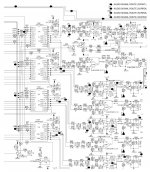
On the filter I have attached in schematic form to the post directly above yours, it does indeed agree with MATLAB. I will do more comprehensive checking (against MATLAB and reality) in due course as I explore more possibilities with this approach.
I guess you need somebody exploiting the LTspiceIV netlist in text format, then converting it into DSP code. Looks also very promising ...
Did you know that LTSpice accepts .wav files as input? So in theory its possible to take your favourite track and then process it through a filter designed in schematic form to see how it would sound (in theory). In the analog filter world of course, theory doesn't always tie up with practice. I have higher hopes for digital filters...
Which audio DSP platform are you targeting ? DSP56K maybe ? The Elektor DSP56374 board ?
Nope, a much cheaper one. See attached pictures - cute eh? Thanks for the links btw
Attachments
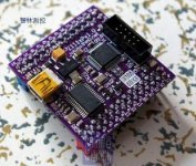
Hey, it reads Cortex-M0 on the PCB. Are you using the ARM Cortex-M0 as DSP engine ? Does it imply that you are using a 32x32 bit multiplication with a 64 bit accumulation ? Looks impressive. But wait a minute, how do you attach a I2S audio DAC on such CPU ? Are you using the built-in serial ports, or a FPGA maybe, so in a nutshell, how do you manage the frame sync and how do you guarantee it remains jitter-free ?DSP56K ? Nope, a much cheaper one. See attached pictures - cute eh? Thanks for the links btw
Hey, it reads Cortex-M0 on the PCB. Are you using the ARM Cortex-M0 as DSP engine ?
Bingo
Well spotted.Does it imply that you are using a 32x32 bit multiplication with a 64 bit accumulation ?
No - the multiply on the M0 is a lot more rudimentary. Perhaps you've been indulging in too much of the M4 user manual - I must confess to salivating on reading all about its DSP extensions
M0 can do 32*32 in one cycle (20nS for the incarnation you're looking at there) but there's no way to handle any overflow so its best to keep the input values to 16 bits or less. Accumulation can be any number of bits (up to the limitation of 14 user registers) so long as the individual products don't overflow 32bits. This means long FIRs are not a problem but coefficients can't easily exceed 16bits.Looks impressive. But wait a minute, how do you attach a I2S audio DAC on such CPU ? Are you using the built-in serial ports
Yes - at the moment one built-in serial port is generating the BCLK and DATA signals, I use a timer output to create WS. That makes up a single stereo I2S channel. The built in FIFO means this is good for up to 4X oversampling. There's a second serial port available for more fancy effects or doing a two way XO potentially (which is in the pipe of course, no timescales yet...).
, or a FPGA maybe, so in a nutshell, how do you manage the frame sync and how do you guarantee it remains jitter-free ?
Frame sync is admittedly a bit of a hack being generated by a timer. Have to set that up empirically which is a bit of a hassle. Its not jitter free yet - I have noticed jitter sidebands on the output of test tones, but they're fairly low in level (below -110dB from memory) so not overly concerned about them just now. A solution is available - use the SSP in slave mode with an external clock - for those who are jitter averse.
Would be fantastic if you manage to hook a S/PDIF receiver and two stereo DACs, for implementing a two-way digital crossover plus a Linkwitz Transform for flattening the deep bass. Clocking the whole stuff from the S/PDIF signal, using a quality S/PDIF receiver as master, is a way to avoid jitter. A digital Linkwitz Transform operating at 96 kHz without decimation requires 32 x 32 bit arithmetics, with 64-bit intermediate results. Have you considered the new Freescale ARM Cortex-M4 processors like the Kinetis K60 maybe ? They may support such 32x32=64 arithmetic, maybe not single cycle. For three-way crossovers, one may cascade two such lovely boards in digital domain using the remaining serial port.ARM as DSP, bingo
Would be fantastic if you manage to hook a S/PDIF receiver and two stereo DACs, for implementing a two-way digital crossover plus a Linkwitz Transform for flattening the deep bass.
I'll have to look into the Linkwitz Transform as I'm not familiar with it. Thanks for the heads up. I think to do the full two-way XO we'd need to go for two M0's (not a big deal as the chips are about 1euro a piece). At present my setup has data coming in off a QA550 wav player through some HC595s. If I want to use the second serial port for output it shares pins I'm already using for that 8 bit parallel input, making things a tad awkward. So I figured perhaps with a two M0 setup we'd not only have more CPU cycles to play around with but also more buffer RAM to handle de-jittering. We might also be able to dispense with a dedicated SPDIF receiver chip (which is already more expensive than the CPU).
Have you considered the new Freescale ARM Cortex-M4 processors like the Kinetis K60 maybe ? They may support such 32x32=64 arithmetic, maybe not single cycle.
I have looked, but to be honest I'm rather lazy about learning new peripherals. I'll muck about with these until NXP's M4s come along. In the meantime there's always the M3s if I run out of CPU grunt.
For three-way crossovers, one may cascade two such lovely boards in digital domain using the remaining serial port.
Actually I was thinking of cascading using the on-board UART as its nicely buffered, then a 3 M0 solution could handle a 4-way XO. Haven't gone anywhere near the UART yet so that's looking a few months ahead.
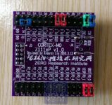
Would be nice to have such tiny lovely PCB replacing one or more AK4383 DACs. Hacking an audio-video receiver this way, you can be multichannel and multiway, all in digital domain. Imagine a USB port for configuring it in a flexible way, basing on a LTspiceIV netlist. See attached picture.
Attachments
@ Abraxalito,
Hardware discussions aside, have you been looking into the level of performance of LspCAD 6.**PRO, Ultimate Equalizer/Sound Easy ord DEQX?
For Hi tec loudspeaker design, anything less ambitious than these packages in terms of filter SPL plus phase optimization and linearization capabilities should not be taken seriously. Now that is quite a task...
I will stay tuned!
Kind Regards,
Eelco
Hardware discussions aside, have you been looking into the level of performance of LspCAD 6.**PRO, Ultimate Equalizer/Sound Easy ord DEQX?
Nope, are any of them open source? Or are they hardware boxes?
For Hi tec loudspeaker design, anything less ambitious than these packages in terms of filter SPL plus phase optimization and linearization capabilities should not be taken seriously.
Ah that's OK then - I'm not so interested in hi-tech, rather appropriate tech for the task at hand. Which, relative to what goes on in commercial DSP these days (see software radio or 4G phone basestations) needn't be very high tech at all. Which is just great because being well off the 'bleeding edge' means we get what we need very cheap
I will stay tuned!
You're welcome - but I will warn you now that if hi-tech solutions are your aim, this will never fit the bill
Sorry forgot to answer post 28. The mentioned programs are rather sophisticated software packages containing loudspeaker filter(x/o) simulators and, more important optimizers.
To my best of knowledge at least LSPcad Pro 6.** and Soundeasy can be used to program e.g. the Behringer 2496. Native software of the Behringer is a bit too simple for more sophisticated filter design, thus leaving the capabilities of the hardware largely unused. I am told these filter packages use Spice engines, but that might be wrong.
Eelco
The aim is really to put together a box of DSP elements (digital bricks if you like) so that DIYers who have little or no experience of DSP can get started in building digital systems by picking the relevant components. That is active systems which are digital all the way up to the final power amp sections. Think of it as rather like a digital audio toolkit, 'Arduino' for audio tweakers.
STM just announced their new range of ARM Cortex M4 chips - here's a link to a dev board which might whet somebody's appetite. Looks like a real bargain at $20 (hat tip jkeny for the link):
STM32 F4 series of high-performance MCUs with DSP and FPU instructions | Dangerous Prototypes
STM32 F4 series of high-performance MCUs with DSP and FPU instructions | Dangerous Prototypes
Something like DSP Concepts AudioWeaver ? ARM Cortex-M4 demo from DSP Concepts - YouTubeThe aim is really to put together a box of DSP elements (digital bricks if you like) so that DIYers who have little or no experience of DSP can get started in building digital systems by picking the relevant components ... Think of it as rather like a digital audio toolkit, 'Arduino' for audio tweakers.
Something like DSP Concepts AudioWeaver ?
Not really what I had in mind because its quite unclear from that short video whether what's shown there can work untethered from the PC. He clicks some objects and that goes over USB to the development board, but how does that all work when there's just a standalone piece of hardware? I'm much more interested in creating some self-contained kit.
Incidentally while we're on the subject of Cortex M4 (one of my favourite subjects
) TI has recently extended its range of Stellaris MCUs into M4 land. Here's a link if anyone's curious - seems they're lower-end devices than those from NXP and STM which makes them nice and complementary. There's no word yet on availability and the dev board is no bargain at $149.LM4F110 Series | Stellaris® ARM® Cortex?-M4-based Microcontrollers | TI.com
The big plus that I can see for these parts from the audio perspective is they all have 4 (yeah, count 'em) SSPs. These ports can be pressed into service as I2S. There are no native I2S peripherals though. Whilst they're relative sluggards at a paltry 80MHz they are claiming some pretty impressively low power specs.
@boggy - Can't see much possibility in open source for a TI-proprietary chip with their own proprietary support toolset. Its the one Bruno's using in his UcD modules isn't it? Fairly good bang for the buck but very limited future prospects being only a single source.
Last edited:
Interesting blog post which provides a bit of perspective and background as to why I'm so keen on Open Source DSP using ARM on a standalone hardware platform - as opposed to doing everything on a PC. The writer's as bullish as I am on Open Source hardware :
Why the Best Days of Open Hardware are Yet to Come bunnie's blog
Why the Best Days of Open Hardware are Yet to Come bunnie's blog
Why not use a Smartphone or a Tablet for configuring an inexpensive, low power, barebone DSP blackbox the size a cigarette packet ?Not really what I had in mind because its quite unclear from that short video whether what's shown there can work untethered from the PC. He clicks some objects and that goes over USB to the development board, but how does that all work when there's just a standalone piece of hardware? I'm much more interested in creating some self-contained kit.
The Smartphone or the Tablet could emulate a DCX2496 panel.
The Smartphone or the Tablet could display a block diagram. Clicking on a block, you could enter new parameters.
The Tablet could display a workspace allowing you to drag and drop elements from a library (adders, substractors, delays, IIRs, FIRs, level control, limiter) for creating your own block diagram.
You would be able to save your own settings and designs, not only on the DSP blackbox, but also on the cloud. This way, you could publish your design and make them available to others. Complex optimizations and measurement sessions could execute on the cloud. Extensive databases containing speaker data and related stuff would be accessible through the cloud.
It all depends the software running on the Smartphone or Tablet. The Smartphone or Tablet would load, connect and configure DSP blocks as code segments into the DSP box. Even if those blocks don't show on the GUI (like in the DCX2496 emulation). This way, all three different GUI approaches decribed above can interact with one common DSP software running into the DSP blackbox.
What is needed inside the DSP blackbox is a PCB containing a decent CPU equipped with Bluetooth, four I2S lanes, one SPI lane, and some expansion connector. The expansion connector is there, for hooking one S/PDIF (or Optical) receiver, one stereo ADC, up to four stereo DACs, and one Asynchronous Sample Rate Converter (ASRC) if needed.
The Freescale Symphony Soundbite Development board (DSP56K family) seems appropriate, provided we can hook a Bluetooth module on the SCI. I guess it is now possible to write the DSP software in C, however the C compiler & debugger may not be "open and free".
The ADI SigmaDSP platform may beat the DSP56K platform if using the increased resolution, and may lead to a more compact PCB because of having DACs on board (what about their quality ?). Is there an "open and free" C compiler & debugger available ?
An ARM Cortex-M4 seems less appropriate, as currently there is no M4 chip equipped with four I2S. How to persuade an M4 to output four I2S lanes, without a FPGA or without a PLD in order to remain low power and low cost ? But on the other hand, surely there are "open and free" C compilers & debuggers available.
Microchip PIC32 MX5/6/7 have four SPI, but can they all operate as I2S ? Same issue as the ARM Cortex-M4.
What would you advise ?
Regards,
Steph
Last edited:
How do you convert spice simulation to dsp code? I think you have some platform in your mind. Can you educate me how you turn it to actual product?
I'm happy to share the assembly source code for what I've so far written. That's an FIR filter implementing that LTSpice simulation (11 tap FIR) running on an LPC1113 (which is a Cortex M0). The LPC1113 system takes in I2S from a QA550 wav player and puts out I2S to my experimental DAC. Would that help you? I'm not sure about the level of detail you'd like or your hardware/firmware experience which is why I ask.
Why not use a Smartphone or a Tablet for configuring an inexpensive, low power, barebone DSP blackbox the size a cigarette packet ?
Now you're talkin'
A low cost, low power, low-EMI open source crossover box is one of the things I'd like to work towards yep.The Tablet could display a workspace allowing you to drag and drop elements from a library (adders, substractors, delays, IIRs, FIRs, level control, limiter) for creating your own block diagram.
You would be able to save your own settings and designs, not only on the DSP blackbox, but also on the cloud. This way, you could publish your design and make them available to others. Complex optimizations and measurement sessions could execute on the cloud. Extensive databases containing speaker data and related stuff would be accessible through the cloud.
Is that kind of software writing something you're comfortable with? Having the user interface on a tablet while the crunching goes on on dedicated hardware is the notion that appeals most to me. Creating a social network around DSP also is very attractive - Facebook for audio-DSP geeks
An ARM Cortex-M4 seems less appropriate, as currently there is no M4 chip equipped with four I2S. How to persuade an M4 to output four I2S lanes, without a FPGA or without a PLD in order to remain low power and low cost ? But on the other hand, surely there are "open and free" C compilers & debuggers available.
Some of the M4 boards from STM are currently winging their way to me, so this is something I'm going to be looking at in the near future. Stay tuned
What would you advise ?
I'm sure you can guess the answer I'm giving! Have your M4 STM 'Discovery' boards arrived yet? I see Mouser's sold out of the first batch. Price has come down from the original $20, now $16. Mine were ordered when they were $15.
- Status
- This old topic is closed. If you want to reopen this topic, contact a moderator using the "Report Post" button.
- Home
- Source & Line
- Digital Line Level
- Open Source DSP XOs