I do not believe so. Other debugging standards like JTAG involve a daisy-chained serial loop, such that multiple chips can be debugged with one connection. However, my understanding is that the Microchip debugger connects directly to a pair of serial lines on a single chip, with no provision for extending the lines to more than one chip.I own a Microchip ICD3 debugger.
Can I program and debug all three chips individually, from a single debug connector ?
Is there something like the ARM "SWD multidrop" debug protocol, in the Microchip world ?
You can also ask this question on the Microchip forum.
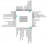
Seems that a chip like PIC32MX534F064H (5.06 eur from Mouser, 64-pin) also benefits from the SPI upgrade supporting I2S. There are three SPI. They could interface a WM8580A Codec for implementing a stereo 3-way crossover with SPDIF-in, Analog-in, and volume control. As all three SPI are taken by the audio lanes, one extra SPI needs to be implemented using bit-banging for controlling the volumes.
Seems that the PIC32MX534F064L (5.67 eur from Mouser, 100-pin) has four upgraded SPI. This way the fourth SPI can be used for controling the volumes, so no bit-banging anymore for controlling the volumes.
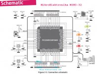
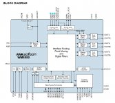
I'm tempted by a MikroElektronika MINI-32 board (25.00 usd), featuring a PIC32MX534F064H inside. Designing a MINI-32 "shield" hosting a WM8580A Codec (5.91 eur from Mouser) would lead to a stereo 3-way crossover with SPDIF-in, Analog-in, and volume control. Don't know if the built-in USB can be used as audio input.
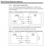
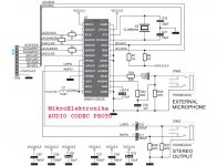
Quite interesting is the MikroElektronika AUDIO CODEC PROTO. This is a tiny board hosting a WM8731 Codec. During months, MikroE remained evasive about how to connect it on a PIC32 SPI. Now with the PIC32 SPI upgrade supporting SPI, it should be a piece of cake. I guess MikroE is now working on sample code for their MINI-32 board when hooking their AUDIO CODEC PROTO.
Seems that the PIC32MX534F064L (5.67 eur from Mouser, 100-pin) has four upgraded SPI. This way the fourth SPI can be used for controling the volumes, so no bit-banging anymore for controlling the volumes.
I'm tempted by a MikroElektronika MINI-32 board (25.00 usd), featuring a PIC32MX534F064H inside. Designing a MINI-32 "shield" hosting a WM8580A Codec (5.91 eur from Mouser) would lead to a stereo 3-way crossover with SPDIF-in, Analog-in, and volume control. Don't know if the built-in USB can be used as audio input.
Quite interesting is the MikroElektronika AUDIO CODEC PROTO. This is a tiny board hosting a WM8731 Codec. During months, MikroE remained evasive about how to connect it on a PIC32 SPI. Now with the PIC32 SPI upgrade supporting SPI, it should be a piece of cake. I guess MikroE is now working on sample code for their MINI-32 board when hooking their AUDIO CODEC PROTO.
Attachments
-
 PIC32MX534F064H - SPI now supports I2S.jpg169.9 KB · Views: 472
 -
 PIC32MX534F064H - three SPI supporting I2S.jpg222.1 KB · Views: 468
 -
 MikroElektronika MINI-32 - three I2S.jpg204 KB · Views: 466
 -
 WM8580A - three I2S.jpg133.7 KB · Views: 404
 -
 MikroElektronika AUDIO CODEC PROTO.jpg148.5 KB · Views: 406
The PIC32MX534F064H should be able to handle USB Audio Class 1 at Full Speed, but you probably have to write your own firmware.PIC32MX534F064H There are three SPI.
PIC32MX534F064L (5.67 eur from Mouser, 100-pin) has four upgraded SPI.
I'm tempted by a MikroElektronika MINI-32 board (25.00 usd), featuring a PIC32MX534F064H inside. Don't know if the built-in USB can be used as audio input.
The 64-pin 'H parts have 3 I2S SPI, the 100-pin 'L parts have 4 I2S SPI.
Wonderful ! Would be nice to have a crossover signal flow like the one I've attached. Is it feasible ?
I have no "linked frequency point" filters - it's a bit more complicated and isnt useful in the real world (imho) - acoustical slopes/response/phase rules the resulting system response, and the filters should flex the acoustical output to specific slopes/Q/freq points...
I don't have multiple-out filters, as everything is based on single pieces of transfer functions which have single input-single output...
Otherwise, it's up to you how would you like to chain the transfer function blocks - "tree", "paralel".
I haven't yet implemented the mixing/substracting of signals - where several outputs are connected to single input... I'll implement it.
You can't make loops of filters...
I'm pretty far from hardware export of filters - i can do biquad coefficients, but signal routing and coefficiencts insertion into DSP source code is out of my reach right now.
Could you please share your DSP sourcecode for the ARM you have?
Probably i'll generate a source for fuctions of DSP blocks in text:
PHP:
float DSP_LP2_x1234(float inSignal, int pos)
{
float a0=0.000001;
float a1=0.000001;
float a2=0.000001;
float b0=0.000001;
float b1=0.000001;
float b2=0.000001;

return (inSignal[pos]*a0 + inSignal[pos-1]*a1 + inSignal[pos-2]*a2)/(inSignal[pos]*b0 + inSignal[pos-1]*b1 + inSignal[pos-2]*b2);
}
with a chaining in the main():
PHP:
void main()
{

float in_0=0;
float in_1=0;

float out_00=in_0;
float out_01=in_1;
float out_10=in_0;
float out_11=in_1;
float out_20=in_0;
float out_21=in_1;

while (1==1)
{
out_00=DSP_LP2_x1534(out_00,x);
out_00=DSP_HP2_x1434(out_00,x);
out_00=DSP_Notch_x1334(out_00,x);
out_00=DSP_Whatever_x1232(out_00,x);

out_01=DSP_LP2_x1534(out_01,x);
out_01=DSP_HP2_x1434(out_01,x);
out_01=DSP_Notch_x1334(out_01,x);
out_01=DSP_Whatever_x1232(out_01,x);

out_10=DSP_HP2_x1555(out_10,x);
out_10=DSP_HP2_x1555(out_10,x);

out_11=DSP_HP2_x1555(out_11,x);
out_11=DSP_HP2_x1555(out_11,x);

x++;
}
}
The sourcecode itself is quite mechanical, and could be generated based on text templates:
PHP:
float $function$ (float inSignal, int pos)
{
float a0=$a0$;
float a1=$a1$;
float a2=$a2$;
float b0=$b0$;
float b1=$b1$;
float b2=$b2$;

return (inSignal[pos]*a0 + inSignal[pos-1]*a1 + inSignal[pos-2]*a2)/(inSignal[pos]*b0 + inSignal[pos-1]*b1 + inSignal[pos-2]*b2);
}
}At this stage, I think that the idea of an open-source DSP Xover would benefit from a fully documented application implementing a stereo 3-way crossover having a fixed structure like the one shown above, only using IIRs, substractors and delays.
There would be a front-end written in Visual Basic, using USB and a Windows PC for modifying values like IIR coefficients and delays.
For calculating the IIR coefficients, we already have IIR_Lab, a design help for digital audio filters. It may suffice in the early days. http://www.diyaudio.com/forums/digi...ir_lab-design-help-digital-audio-filters.html
No doubt there can be more elaborate front-ends running on Windows, providing graphics, relying on Visual Basic or anything else. At the moment, I guess that most developers will want to keep their front-ends proprietary, and I fully respect such approach.
As shown above, if the PIC32 redesigned SPI can synchronize three SPI in audio (aka I2S) mode, a proof of concept can be designed right now using one MikroE MINI-32 and one MikroE AUDIO CODEC PROTO (Codec in Master Mode). The oscilloscope can easy tell if all three SPI outputs remain in sync. If all three SPI outputs remain in sync, it will be time for designing a "shield" for the MikroE MINI-32, hosting a WM8580 Audio Codec.
As soon as there is an Embedded Artists LPC43xx LPCXpresso board, more computing power will be possible.
Interesting topic, thanks for sharing your ideas. I looked at the STM32F4 and i must say i'm impressed.
s3tup, if your code is implementing a biquad, then it's not OK. You need a buffer for the output signal, and forget about dividing terms. Division is nearly heresy in DSP
[...] I'm pretty far from hardware export of filters - i can do biquad coefficients, but signal routing and coefficiencts insertion into DSP source code is out of my reach right now.
Could you please share your DSP sourcecode for the ARM you have?
Probably i'll generate a source for fuctions of DSP blocks in text:
PHP:float DSP_LP2_x1234(float inSignal, int pos) { float a0=0.000001; float a1=0.000001; float a2=0.000001; float b0=0.000001; float b1=0.000001; float b2=0.000001; return (inSignal[pos]*a0 + inSignal[pos-1]*a1 + inSignal[pos-2]*a2)/(inSignal[pos]*b0 + inSignal[pos-1]*b1 + inSignal[pos-2]*b2); }
s3tup, if your code is implementing a biquad, then it's not OK. You need a buffer for the output signal, and forget about dividing terms. Division is nearly heresy in DSP
chaparK,
That sourcecode is just example... Actual code will have all the in/out buffers, and proper biquad implementations...
As i think of it, it's enough to write a piece of efficient code in ASM, and then integrate it to the code-generator routine... in the other hand, these compilers tend to optimize the code pretty good...
Wonderful ! Would be nice to have a crossover signal flow like the one I've attached. Is it feasible ?
Nice GUI... is the your code too?
")
Xover is a visual basic application used as front-end, designed for sending parameters to any DSP, provided it is running open source code. As I would like to generate some revenue from it, I don't intend distributing Xover as is, but instead, I intend transforming it into a web based application, asking 0.99 $ each time the DSP gets flashed. No money asked when you change parameters. Money only asked when you want the changes to become permanent. At the moment I have no idea what kind of web-based framework I may use.Nice GUI... is the your code too?
Hi,
Thought I would chime in on here. I'm developing a board using the DM8148. It has a 1Ghz A8 and a 750MHz C674x DSP. I've also maximized the pin mux settings to allow a possible 26 pair pairs of i2s I/O.
More can be found here
DaVinci Digital Video Processor - TMS320DM814x SOC - TMS320DM8148 - TI.com
My genius coder is at work on the Mistral EVM to allow 10 simultaneous pairs of i2s or DIT output on McASP0 at 24-bit 96KHz.
By the sounds of things you can port your work to the DM8148.
Here's the initial hardware spec sheet.
http://www.lucidchart.com/publicSegments/view/4f119bb5-5054-47cf-a4fe-5f7d0a48117a
Very promising. I am a big fan of the TMS320 family and have significant experience programming these DSP chips in C and assembly.I'm developing a board using the DM8148. It has a 1Ghz A8 and a 750MHz C674x DSP. I've also maximized the pin mux settings to allow a possible 26 pair pairs of i2s I/O.
My genius coder is at work on the Mistral EVM to allow 10 simultaneous pairs of i2s or DIT output on McASP0 at 24-bit 96KHz.
Question: Why did you only use 5 of the McASP peripherals and not all 6? Were those particular pins needed for other critical functions?
When you spec 26 pairs, that implies that you have connected McASP5, McASP4, McASP3, McASP2 and McASP0. What about McASP1? It is the only other McASP peripheral which can accept an independent receive clock (bit and word frame). The remaining McASP peripherals only have output clocks, and are thus seemingly no good for receiving data that is externally clocked. For example, it might be nice to have HDMI audio input on McASP1 and AES3/SPDIF input on McASP0, although I admit that those are clock-compromised standards.
When you say 10 simultaneous pairs, I assume that you mean 10 simultaneous stereo streams. McASP0 only has 10 pins that can operate as data receive or data transmit, but not both at the same time. However, I get the impression that the system could handle 10 simultaneous multichannel-surround streams, provided they all used the same format. EDIT: When I say multichannel-surround, I am thinking not only of, e.g., 7.1 full-range surround but also multi-way crossover outputs for a single speaker cabinet with multiple drivers.
Last edited:
By the sounds of things you can port your work to the DM8148.
I reckon people could, but I'd not recommend it. Your project has rather different philosophy to mine. If you recall, you said:
sgpu said:RF is our nightmare but somewhere along the line you have to compromise on noise.
My idea is not to compromise on noise and hence use only enough MIPs to get the job done.
We have
McASP0 - 10 data pins
McASP1-4 - 4 data pins each.
Each McASP has two time domains. So you can xm and rx at whatever you like simulaneously but the format must remain the same. Ie, xm 24/96 i2s, rx 16/44.1 i2s. We have 5 pins xmit and 5pin rx on McAS0. Also, each pin can xm/rx TDM to supported ADC/DAC chips...
McAsp 5 not used as pin muxed with mcasp4.
Hi,
Thought I would chime in on here. I'm developing a board using the DM8148. It has a 1Ghz A8 and a 750MHz C674x DSP. I've also maximized the pin mux settings to allow a possible 26 pair pairs of i2s I/O.
More can be found here
DaVinci Digital Video Processor - TMS320DM814x SOC - TMS320DM8148 - TI.com
My genius coder is at work on the Mistral EVM to allow 10 simultaneous pairs of i2s or DIT output on McASP0 at 24-bit 96KHz.
By the sounds of things you can port your work to the DM8148.
Here's the initial hardware spec sheet.
http://www.lucidchart.com/publicSegments/view/4f119bb5-5054-47cf-a4fe-5f7d0a48117a
Isn't that a fine pitch BGA part ?? Who's going to solder that on for you ?
Soldering? A favor from a local assembly firm, I know the directors.
Lifted from 16.1 of the TRM ( http://www.ti.com/lit/ug/sprugz8/sprugz8.pdf )
"The McASP consists of transmit and receive sections that may operate synchronized, or completely independently with separate master clocks, bit clocks, and frame syncs, and using different transmit modes with different bit-stream formats. The McASP module also includes serializers that can be individually enabled to either transmit or receive."
Question: Why did you only use 5 of the McASP peripherals and not all 6? Were those particular pins needed for other critical functions?
The pin mux utility is very useful here. We could increase McASP1 to 8 data pins but we would lose 2 data pins off McASP3,4 as a result.
Question: Why did you only use 5 of the McASP peripherals and not all 6? Were those particular pins needed for other critical functions?
Pin muxing makes it quite difficult to have all McASP units active. I made the decision to keep a few quads for 8ch i2s per McASP. McASP3,4,5 were intended to be outputs. I will be adding external CLKin options for each of these too if an external board has its own master clock that the McASP can slave from.The remaining McASP peripherals only have output clocks, and are thus seemingly no good for receiving data that is externally clocked.
Not true. Saying that, there is not a great deal of support in the recent PSP for any of what I'm planning. I have a developer extending the EVM McASP and ALSA driver. Initially, each McASP module will be presented to linux as independent sound cards for testing. The pin muxing, for now, will be set with the boot loader. I need advice whether or not this can be changed on the fly through registers.McASP0 only has 10 pins that can operate as data receive or data transmit, but not both at the same time.
I am deciding what to do about a master onboard clock. I can install install several low noise master clocks if needed. Using registers, each McASP time domain can be set to use clocks from the internal PLL, or XO. The clock structure on the DM8148 needs some serious thought.
Last edited:
Soldering? A favor from a local assembly firm, I know the directors.
Lifted from 16.1 of the TRM ( http://www.ti.com/lit/ug/sprugz8/sprugz8.pdf )
"The McASP consists of transmit and receive sections that may operate synchronized, or completely independently with separate master clocks, bit clocks, and frame syncs, and using different transmit modes with different bit-stream formats. The McASP module also includes serializers that can be individually enabled to either transmit or receive."
what development system do you use to write code for this device ??
Whatever floats your boat for linux development. The board will run a wide variety of OS. I am currently booting Ubuntu or Gingerbread on the EVM. Have you come across the BeagleBoard before? I'm building a more powerful version of that.what development system do you use to write code for this device ??
Last edited:
I don't want to hijack this thread. I started another here http://www.diyaudio.com/forums/pc-based/203712-arm-dsp-based-open-source-hi-fi.html
Clock wise my initial plan was to have three good low noise clocks.
- AUXOSC is routed to most of the A/V subsystems including HDMI by way of an internal PLL.
- XREF are external fixed clocks. Developers will be able to chose which clock source to use for their McASP xm/rx domain. Either the internal PLL from AUXOSC or between two low noise ref clocks for 44.1/48 sampling rates.
I will be running some tests in a few weeks by backfeeding McASP0 outputs to McASP1 inputs to check the PCM streams bit for bit. I will also be testing using the clock sources on the EVM. You can buy these for $2000 from TI. Info and schematics here. http://www.mistralsolutions.com/pes-support/support-downloads/tmdxevm8148.html The EVM uses a http://search.digikey.com/us/en/products/CSX750FBC24.576M-UT/300-7245-1-ND/482133 to distribute clocks to the AIC32 and XREF.
Last edited:
- Status
- This old topic is closed. If you want to reopen this topic, contact a moderator using the "Report Post" button.
- Home
- Source & Line
- Digital Line Level
- Open Source DSP XOs