I guess you refer to post #113 : breaking a LPC1343 LPCXpresso board in two parts, only using the JTAG Debug Probe section. I have three objections.JTAG/SWD Segger J-Link Debug Probe at 300 dollars or JTAG/SWD Red Probe+ at 150 dollars : no need to spend so much - check out the link I've given above to an eBay option.
1. The JTAG Debug Probe section of the LPC1343 LPCXpresso board contains a NXP LPC3154 chip. Download the datasheet. The NXP LPC3154 combine an 180 MHz ARM926EJ-S CPU core, High-speed USB 2.0 OTG, 192 kB SRAM, NAND flash controller, flexible external bus interface, two I2S (I2S0 and I2S1), a Stereo Audio Codec hooked on I2S1, Li-ion charger, Real-Time Clock (RTC), serial and parallel interfaces. The LPC3154 are implemented as a multi-chip module with two side-by-side dies, one for digital functions and one for analog functions, which include Power Supply Unit (PSU), audio codec, RTC, and Li-ion battery charger. Such chip having two I2S, it is a waste to use it as USB to JTAG bridge, for debugging a low cost ARM chip like the LPC1343 providing no I2S.
2. Do you hope using the LPC3154 side of the LPC1343 LPCXpresso board, as JTAG Debug Probe for any kind of ARM chip, say the Cortex-M4 Freescale K10 (one I2S providing two I2S lanes) or the T.I. Cortex-A8 AM3358 (two McASPs providing eight I2S lanes) ? Have you checked this ? Won't you expect that the NXP firmware burned into the LPC3154, is only tolerating a JTAG connexion on a NXP LPC1343 as target ? Using the LPC3154 side of the LPC1343 LPCXpresso board, and turning it into a "open" JTAG Debug Probe sounds like an urban legend.
3. Even if today NXP has not locked the NXP LPC3154 firmware for only connecting on a NXP LPC1343, as soon as they know somebody gets a successfull JTAG connexion on any another chip than the NXP LPC1343, they will take countermeasures. And, while designing a digital audio crossover, I won't spend time in developing counter-countermeasures.
Now consider the PIC32MX1 and PIC32MX2 and the Microchip ICD3 Debug Tool at 200 dollars. See how they put you out of trouble regarding the debug. And remember : the PIC32MX1 and PIC32MX2 provide two I2S, even in their 28-pin variants.
Cortex-M4 is not mature yet for multichannel digital audio. Currently we miss Cortex-M4 chips featuring four I2S or one McASP.
The NXP LPC4300 is too complicated (no built-in Flash, two asymetric cores, SGPIO hard to configure).
Given this, if I need more CPU power and more than two I2S lanes, I'm only interested into the T.I. AM3358 Cortex-A8. Can somebody advise a proper AM3358 toolchain, BeagleBone compatible, easy to setup, with a decent cost, preferably not bloated by a Linux kernel ? I'm ready to spend 150 dollars for the the Red Probe+ but I'm not sure I can get a toolchain working the way I want, supporting bare metal programming enabling me to write and debug all Audio DSP routines in Cortex-A8 assembly code. Can somebody advise me, by experience ?
Last edited:
Have a look at this vid and see if any of your objections are addressed to your satisfaction:
Debugging Applications with NXP LPCXpresso - YouTube
Debugging Applications with NXP LPCXpresso - YouTube
Looks indeed that an urban legend translated into some reality ...Have a look at this vid and see if any of your objections are addressed to your satisfaction
LPC1227 LPCXpresso LPC-Link | Embedded Artists AB
What are the supported ARM microcontrollers ?
Last edited:
Cortex-M0+ Processor - ARM
This baby does about 0.9MIPs/MHz so in practice its going to be able to comfortably run 10MMACs - say a 256 tap filter @44k1 for a power budget around 2mW at 100MHz on a 90nm process at a price projected to be under $0.40")
This baby does about 0.9MIPs/MHz so in practice its going to be able to comfortably run 10MMACs - say a 256 tap filter @44k1 for a power budget around 2mW at 100MHz on a 90nm process at a price projected to be under $0.40
You might be surprised. Just don't hold your breath.
OK lets see the goodies
Why not XMOS
Hello, this is my first post here so I excuse myself in advance if I missed something that was said before. I am right now building a pair of Orions, and would like to see how they sound with a DSP crossover. I find the prospect of having an open source DSP really good. However, having played around with a few DSPs and ARM processors, I find that the main difference is that in DSP you have a short code (you usually execute it all for each sample) which is executed synchronously. There is not much that can go wrong.
On ARM however you can never guarantee at what cycle a particular instruction will be executed. Just an interrupt can take up to 40 cycles while the registers are dumped into memory, etc. However, for open source I understand that specialized DSPs such as ADI or TI are not really an option.
I have worked a bit with the XMOS chips, and they do offer a great number of advantages for this type of application:
- fast: up to 4 cores, 500 MHz, 8 threads per core each with its own set of registers, single cycle MACC (32*32->64)
- synchronous: the exact time of execution of each instruction is deterministic to the cycle.
- flexible, reconfigurable I/O, you can have loads of I2S I/O
- loads of open source audio related code already exists: https://github.com/xcore/sc_dsp_filters
- development boards are affordable and the main development environment is open source, whereas with ARM the "standard" ones are commercial.
The chip is rather flexible, and we have used it as a MOSFET "controller" for a digital class D amplifier, where you really need to make sure that both transistors do not open at the same time. We could adjust the delays between the individual pins to about 3ns dynamically. Really impressive.
For biquads, it has been tested to do 20/thread at 48kHz, potentially you could use three cores (for woofer, midrange and tweeter), and one for doing the I/O.
With a few hundred biquads should be sufficient for most things.
I don't have that much time, but I can definitely find a couple of hours to test things out in the case more information is useful.
Hello, this is my first post here so I excuse myself in advance if I missed something that was said before. I am right now building a pair of Orions, and would like to see how they sound with a DSP crossover. I find the prospect of having an open source DSP really good. However, having played around with a few DSPs and ARM processors, I find that the main difference is that in DSP you have a short code (you usually execute it all for each sample) which is executed synchronously. There is not much that can go wrong.
On ARM however you can never guarantee at what cycle a particular instruction will be executed. Just an interrupt can take up to 40 cycles while the registers are dumped into memory, etc. However, for open source I understand that specialized DSPs such as ADI or TI are not really an option.
This should not be an issue. Even on ADI dsp's interrupt latencies can be as long as 200 dsp cycles depending on the type of context switching you use. The important aspect of this is that as long as the latency does not consume the whole audio cycle then there will always be plenty of time to process the audio word and write it out to the serial port FIFO. Some DSP's such as the ADI offer block mode processing which means that a block of N samples is processed sequentially and the interrupt interval is lengthened by N audio cycles so that the latency becomes a smaller portion of the audio processing. I assume the ARM would be similar.
I had a look at the Xmos but I don't think it offers floating point processing which is something I needed at the time otherwise it's a pretty impressive chip ideal for real time systems where you would otherwise use an RTOS. You can get floating point on the Cortex M4 which is handy to have
regards
Trev
Last edited:
On ARM however you can never guarantee at what cycle a particular instruction will be executed. Just an interrupt can take up to 40 cycles while the registers are dumped into memory, etc.
If you're running the whole code for every cycle, why would you need interrupts at all? Or are you wanting to update parameters based on user input in real-time. I could see there that interrupts might come in handy.
I have worked a bit with the XMOS chips, and they do offer a great number of advantages for this type of application
I too looked at XMOS in considerable detail, and rejected it for a number of reasons for my designs. I agree technically it looks great based on performance figures. But then after I ordered an eval module I got to discover that the commercial side of their organisation isn't up to the same standards as the technical. That experience got me looking into other options and I eventually settled on ARM. After making my decision I sent feedback to XMOS and I explained to their CTO my reasons for not going with XMOS and why I see that ARM will eventually eat them. Nothing in his replies made me change my mind - indeed I received further confirmation that my decision was the correct one
Incidentally there's a recent EETimes short article here where its not clear that they have yet built up a sustainable business. They've sold half a million devices in USB it says (since inception in 2005) - and now they've introduced a dual-die part with USB PHY. I can't see the sense in that myself, for what seems such a small market. In high speed USB, there's already custom silicon which does the job better and at much lower power and its on the same die as many ARM CPUs.
Thanks for all the information, I agree that if XMOS have strange commercial practices (like their weird USB audio driver licensing) it is best to stay away. It's a pity because I find the architecture rather elegant and having a free IDE is a definite plus. Lack of fast floating point is a strong minus.
I have now read through this thread in detail, I had not realized that the XMC4500 and LPC4300 were maturing this quickly and had cheap development boards available. The cortex M4 is attractive, apart for the low clock speed. I guess the A and R versions don't have enough I2S I/O though.
It is a real pity that a DSP like SHARC does not have an open source toolchain (even just a bootloader and an ASM), as the M4 (and XMOS) are probably much slower, even at the same clock speed as I guess stuff like getting coefficients from memory, clocking samples in and out etc take at least one instruction each whereas it happens automatically on DSPs.
The guys at miniDSP seem to have done a great job, but not open source of course. I wonder where they got the spec on how to program the SigmaDSP without Sigma Studio, of if they just looked at the code that Sigma Studio generates and used that.
Thanks for all the information, I agree that if XMOS have strange commercial practices (like their weird USB audio driver licensing) it is best to stay away. It's a pity because I find the architecture rather elegant and having a free IDE is a definite plus. Lack of fast floating point is a strong minus.
XMOS to me is also very elegant but I see its market niche shrinking. They're already on 65nm so not very low power (due to leakage and the high clock rate). Whereas the only M4 part on 65nm is (I think) TI's and it looks like they've hamstrung that one to just 80MHz so as not to eat into their other DSP. Which to me looks crazy coz people will just buy other people's M4 parts when they need >80MHz.
I have now read through this thread in detail, I had not realized that the XMC4500 and LPC4300 were maturing this quickly and had cheap development boards available. The cortex M4 is attractive, apart for the low clock speed. I guess the A and R versions don't have enough I2S I/O though.
STM's dev board (I have several but not powered them up yet) is seriously cheap, presumably as a marketing exercise. But not many I2S.
It is a real pity that a DSP like SHARC does not have an open source toolchain (even just a bootloader and an ASM),
I don't see that as a pity - to my way of thinking its more lead in ARM's pencil
Another interesting technology which is coming up is the mixed ARM/FPGA processors such as Xilinx Zynq 7000, which does have an open source environment. I personally find FPGA programming quite difficult, but last year I have tried (for work) the Actel smartfusion, which is a cortex M3+FPGA. You program it just like any other ARM, say with Keil, but with the possibility of adding custom ports/DSP instructions etc. The design tool then generates the c drivers automatically, and you just call the functions from your ARM code.
For an open platform and FPGA does offer some advantages, and they have really come down in prices in the last few years (the Actel dev board was 90$).
For an open platform and FPGA does offer some advantages, and they have really come down in prices in the last few years (the Actel dev board was 90$).
Another example of using LTSpice in FIR filter design
OK, now getting back to the original purpose of this thread, which was to encourage people to try out LTSpice as a digital filter design tool and hence establish a base of 'open source' digital filter designs.
Here's a design flow I've played around with this week as a rather different way to design digital FIR filters than the traditional MATLAB and equiripple style approach. As Julian Dunn pointed out in a paper, there are some hidden pitfalls of using equiripple filters in digital audio. Bruno Putzeys has picked up on his paper too. In a word - time smearing.
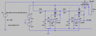
So in an attempt to avoid time smearing I decided to explore how using an analog filter as a template for a digital one might work out. Here's a 4th order MFB lowpass that I'd like to have as a digital filter. Its the LP half of what I've been using (LR4) in my active speakers of late. But here you'll notice there's a delay line for the HP rather than the traditional two opamp Sallen-Key - the idea here is that with digital filters we can use delay elements for free (unlike with analog filters) so why not build a subtractive cross-over? Doug Self points out in his recent book on active XOs that subtractive XOs have the weakness in analog implementations that they depend on matching for their stop-band performance. Well in digital, matching doesn't need to be an issue.
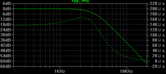
LTSpice allows us to set up both frequency response and time domain characterisations - I've done that here. First check the frequency domain performance is what we expect. Then do a time domain analysis with a single cycle impulse - given that this is to work at 44k1, a pulse 22.7uS wide is chosen. By trial and error I fiddled the group delay (integrator time constants) to match an integer number of samples (6 in this case) - the precise crossover point isn't as important as getting the right delay.
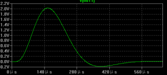
With the delay line matching the filter's asymptotic group delay, the HP subtracted output looks like the last plot.
OK, now getting back to the original purpose of this thread, which was to encourage people to try out LTSpice as a digital filter design tool and hence establish a base of 'open source' digital filter designs.
Here's a design flow I've played around with this week as a rather different way to design digital FIR filters than the traditional MATLAB and equiripple style approach. As Julian Dunn pointed out in a paper, there are some hidden pitfalls of using equiripple filters in digital audio. Bruno Putzeys has picked up on his paper too. In a word - time smearing.
So in an attempt to avoid time smearing I decided to explore how using an analog filter as a template for a digital one might work out. Here's a 4th order MFB lowpass that I'd like to have as a digital filter. Its the LP half of what I've been using (LR4) in my active speakers of late. But here you'll notice there's a delay line for the HP rather than the traditional two opamp Sallen-Key - the idea here is that with digital filters we can use delay elements for free (unlike with analog filters) so why not build a subtractive cross-over? Doug Self points out in his recent book on active XOs that subtractive XOs have the weakness in analog implementations that they depend on matching for their stop-band performance. Well in digital, matching doesn't need to be an issue.
LTSpice allows us to set up both frequency response and time domain characterisations - I've done that here. First check the frequency domain performance is what we expect. Then do a time domain analysis with a single cycle impulse - given that this is to work at 44k1, a pulse 22.7uS wide is chosen. By trial and error I fiddled the group delay (integrator time constants) to match an integer number of samples (6 in this case) - the precise crossover point isn't as important as getting the right delay.
With the delay line matching the filter's asymptotic group delay, the HP subtracted output looks like the last plot.
Attachments
Turning an analog filter into a digital one
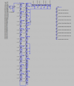
The next step is one I'd like eventually to automate - I'm sure its not hard to do that, but I did this manually to get a feel for what goes on. I tabulated the impulse response plot, having normalized it (by trial and error) to get 1LSB = 1mV. I decided to go for 12bit coefficients, which means 2.047V is the maximum representable amplitude. To do this, just scale the amplitude of the impulse to get the peak close to the maximum digital value. I needed 11.8V to achieve 2.031V as a peak value (the waveform goes slightly beyond this between samples).
The values of the impulse function I wrote down at intervals of the sample rate (22.6uS approx). These values then become the coefficients for the FIR filter which we build using delay elements.
The pic is a little cramped owing to not having too much resolution on my screen, but down the left are the coefficients expressed as a column of .param's - the summation is done with the series voltage sources over at the right.
Attachments
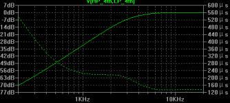
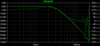
Here's what the synthesized FIR looks like in the frequency domain
The stop band has wiggles - these are the result of both quantizing the coefficients to 12bits and truncating the impulse response in time to a relatively small number of samples (31 in this case). I've not used any windowing function to smooth off the discontinuities just tweaked the final few coeffs by hand to see how the stop band wiggle shifts around.
The stop band has wiggles - these are the result of both quantizing the coefficients to 12bits and truncating the impulse response in time to a relatively small number of samples (31 in this case). I've not used any windowing function to smooth off the discontinuities just tweaked the final few coeffs by hand to see how the stop band wiggle shifts around.
Attachments
Last edited:
I haven't gotten around to building a digital XO in this way yet but I hope to do so sometime this year The computational complexity is low in going for such an arrangement - the FIR has 31 taps meaning fewer than 3MMACs for a stereo one. The highpass is just a subtraction, so not exactly taxing An LPC1113 will be able to manage this mathematical burden very comfortably - indeed it probably would be able to be underclocked which would mean the power demands are going to be single digit mA (at 1.8V) - doing it with 5532s would take 4 chips and 320mW.
The computational complexity is low in going for such an arrangement - the FIR has 31 taps meaning fewer than 3MMACs for a stereo one. The highpass is just a subtraction, so not exactly taxing An LPC1113 will be able to manage this mathematical burden very comfortably - indeed it probably would be able to be underclocked which would mean the power demands are going to be single digit mA (at 1.8V) - doing it with 5532s would take 4 chips and 320mW.
Last edited:
Call it my rebellious streak. I can understand better what's going on with FIRs, and don't have any kind of intuitive handle on how IIRs work or what their shortcomings might be (limit cycles, potential truncation effects). Until I find I'm out of computational power I prefer to stick to FIRs
- Status
- This old topic is closed. If you want to reopen this topic, contact a moderator using the "Report Post" button.
- Home
- Source & Line
- Digital Line Level
- Open Source DSP XOs