I had a PM again asking me how to use SEN with PCM1794.
I don't have a 1794, so I am not the best person to answer that question.
Instead, if you would use the "Search this thread" function at the top of this thread, and type "PCM1794", you will find in post #656, 812, 814, 815, & 818 where apparently that it has been done before, successfully.
Perhaps those who used SEN with PCM1794 can also give you help if you have further, specific questions.
Thank you for your interest,
Patrick
Sen PCM1794A
I'm still using/experimenting with Sen/#998 and PCM1794A.
I'm still using the servo in post #818.
Since posting previous measured results I have modified my sound card to remove the input buffer op-amps and coupling capacitors and connect to the next stage of the input section directly - this gives me two balanced inputs to the sound card. I have also fixed some grounding issues and have replaced a dead rechargeable cell in the floating power supply.
The net of these changes is that I'm getting better measured results now than in any of my previous postings.
Most of my problems have been in the implementation details - ground loops and oscillation and the dead cell (2nd harmonic with the dead cell was sweet, considering putting it back ;-).
I have also experimented with numbers of parallel jfets and also with the circuit variant in #998.
I have learned the following from making a lot of mistakes:
1) The bias servo in #818 is good enough for me. I haven't tried anything else since (it's possible it has contributed to the oscillation problems I've had though).
2) RM in #998 sounds bad.
3) #998 with RM=0 has spectacularly good high frequency sound. (The component values in the #998 post are wrong for PCM1794A, you need to use lower Riv (RLA1/RLB1) according to the output voltage you want - Vpk-pk on each balanced half=2*Riv*0.0039).
4) You need to remember that Riv and the electrolytic capacitors connecting Riv to the floating supply form a high pass filter so these capacitors need to be large enough to avoid low frequency roll off and low frequency distortion. If you decrease Riv you need to increase these capacitors (and also increase Civ) if you want the frequency response to stay the same.
5) It's possible to blow those capacitors up. Since I've been using two electrolytics back-to-back to make one bipolar capacitor for each I haven't had any more problems. When you do this you need to make them twice as big again to get the same low frequency response you had before.
6) It's possible to get spectacularly good sound using ordinary electrolytics for these capacitors.
7) Civ needs to be chosen with care and a listening test - it is very audible.
8) The number of jfets in parallel is significant. I think there is some benefit in getting the input impedance down and some additional benefit in keeping the fraction of the current swing down to a small fraction of the bias current. You can definitely make a really spectacularly great sounding circuit with 6 parallel pairs. I haven't managed to get my 4 parallel pair circuit sounding so good yet but many other variables have changed.
9) Trying to drive long cables from the Sen output can cause oscillation which can be fixed by putting a small resistor in series in the signal cable at the Sen output - I only tried 50R which worked to kill the oscillation.
10) Heatsinks on the jfets don't seem to be essential.
11) If you are going to use heatsinks then you need separate heatsinks for the left and right channels and for the two halves of a balanced pair otherwise you may get oscillation.
As long as you make sure to match at least one pair of jfets separately for the special pair in #998 then the difference between a Sen implementation and #998 is only a couple of connections changed (the other jfets can be matched as a group for the top half and a group for the bottom half). I have switched back and forth a few times as I have fixed issues in my implementation to try to give the circuits a fair comparison. #998 was more problematic to get sounding good - Sen was sounding great and #998 awful when I had some grounding issues and Sen was driving cables which would cause #998 to oscillate. But with the issues fixed I think it is worth doing a listening test between the two. I'm currently working on a new attenuator before I make a final decision.
I want to try moving a fraction of Riv of the Sen instance to the other end of the cable, putting it into the amp and switching it with relays. So there will be a bit of Riv series resistance in each leg at the Sen output and the remainder to ground at the input stage inside the amp. i.e. a current output to the amp rather than a voltage output. I don't know if this particular idea will work well.
In summary: Sen works with PCM1794A and can be made to sound fantastic. You need something to sink the bias current. The servo in #818 is OK. EUVL also made some simpler suggestions which you might want to try instead. I also think the variant in #998 is worth listening to. #998 can have really spectacularly good treble.
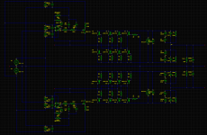
PCM1794A Sen and #998
Here are schematics for Sen and #998 which work with PCM1794A.
I have tried these component values but I would make C3,4,5,6,10,11,12,13 bigger to improve the low frequency response. 1000uF may be better.
I'm currently experimenting with Sen with 4 parallel pairs as shown and #998 with 3+1 pairs as shown in the other diagram (with no heatsinks). Eventually, I expect to go back to my previous best version which has 7 pairs in Sen mode or 6+1 in #998 mode (and heatsinks) and which I expect to sound better than the 4 pair version.
CLA1, CLA2 you have to play with to suit your taste and the cables you have got. I have tried from 0 to 4.7nF. These caps are critical to sound quality.
Don't be tempted to add a small ceramic cap to C17 or C26. The electrolytics are good on their own.
I used NiMH AA cells throughout and shared the servo supply between L+R channels. I got it to work with good channel separation but grounding was a pain because my Sen is in a separate enclosure from the DAC chip so I had to send the bias return for both L+R channels down only one cable to avoid a ground loop. Two servo supplies would have been symmetrical.
Layout, grounding and op-amp decoupling is critical to avoid distortion from the servos and oscillation. I have tried to show in the diagram roughly how the decoupling and grounds are connected.
My servos and Sens are laid out back to back - you can bend all the pins of a DIP8 package to point upwards to get the right pinout to make a mirror image circuit.
I didn't actually have a complete schematic and just threw this one together to answer a PM. So, sorry in advance for possible DAC toasting mistakes.
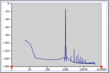
Measurement is full scale output into the PCM4220 datasheet ADC balanced input buffer and is at -13.1dB (i.e not normalized to 0dB). I can get better measurements if I increase Riv to get full scale input of the ADC.
DAC and ADC are running from the same master clock and the sampling rate is 88.2kHz which I like best for CD music (after sample rate conversion).
The diagrams only show one balanced channel with +, gnd, - inputs on the left and outputs on the right. You need two for stereo.
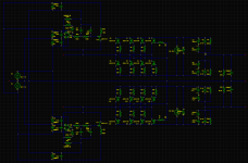
Here are schematics for Sen and #998 which work with PCM1794A.
I have tried these component values but I would make C3,4,5,6,10,11,12,13 bigger to improve the low frequency response. 1000uF may be better.
I'm currently experimenting with Sen with 4 parallel pairs as shown and #998 with 3+1 pairs as shown in the other diagram (with no heatsinks). Eventually, I expect to go back to my previous best version which has 7 pairs in Sen mode or 6+1 in #998 mode (and heatsinks) and which I expect to sound better than the 4 pair version.
CLA1, CLA2 you have to play with to suit your taste and the cables you have got. I have tried from 0 to 4.7nF. These caps are critical to sound quality.
Don't be tempted to add a small ceramic cap to C17 or C26. The electrolytics are good on their own.
I used NiMH AA cells throughout and shared the servo supply between L+R channels. I got it to work with good channel separation but grounding was a pain because my Sen is in a separate enclosure from the DAC chip so I had to send the bias return for both L+R channels down only one cable to avoid a ground loop. Two servo supplies would have been symmetrical.
Layout, grounding and op-amp decoupling is critical to avoid distortion from the servos and oscillation. I have tried to show in the diagram roughly how the decoupling and grounds are connected.
My servos and Sens are laid out back to back - you can bend all the pins of a DIP8 package to point upwards to get the right pinout to make a mirror image circuit.
I didn't actually have a complete schematic and just threw this one together to answer a PM. So, sorry in advance for possible DAC toasting mistakes.
Measurement is full scale output into the PCM4220 datasheet ADC balanced input buffer and is at -13.1dB (i.e not normalized to 0dB). I can get better measurements if I increase Riv to get full scale input of the ADC.
DAC and ADC are running from the same master clock and the sampling rate is 88.2kHz which I like best for CD music (after sample rate conversion).
The diagrams only show one balanced channel with +, gnd, - inputs on the left and outputs on the right. You need two for stereo.
Attachments
Last edited:
Hi Patrick, I received some months ago my SEN I/V 18, and now I'm building the power supply,the Salas shunt. I read your article on Linear Audio, where you said that the voltage can be also of 27 or 36 volts. I would feed the SEN I/V with 24 volts. Can I do it? Can I get some heat issue cause the higher transimpedance of K369 ?
Thanks.
Thanks.
Datasheets says 2SK369V in TO92 package can dissipate 400mW to free air.
Heatsink can only help.
With 24V across 2 FETs (upper & lower), and each having an Idss of say 25mA, dissipation / FET = 300mW.
So yes, they are within manufacturer's specification.
But then with a total of 6V output swing (pk-pk), 24V is a bit over the top, shall we say.
Patrick
Heatsink can only help.
With 24V across 2 FETs (upper & lower), and each having an Idss of say 25mA, dissipation / FET = 300mW.
So yes, they are within manufacturer's specification.
But then with a total of 6V output swing (pk-pk), 24V is a bit over the top, shall we say.
Patrick
Even though most of you seem to recommend batteries, i will probably build four separate shunt-regs and use each of one winding each.
Since i would want a shunt-reg, and not to much heat, i have been looking at something like this:
Simple Voltage Regulators Part 1: Noise
It's the first regulator there, but with R2 changed to CCS, and also adding a 2x100mH common mode choke filter/large cap before the CCS, and a zobel network at the output. I would like to keep it simple, and compact design - which is why this looks as my best alternative so far.
If batteries isn't an alternative, what do you guys think about this design - would it be enough, or is there anything else i should think about.
>Even though most of you seem to recommend batteries, i will probably build four separate shunt-regs and use each of one winding each.
I have tried separate secondaries (toroids) and I had serious noise issues. I tried a couple of different regulators, but no go. The noise does not seem to have anything to do with the quality of the regulator. Be warned.
I might try with R-cores, or separate toroids - one day.
For now I have absolutely no reason to downgrade from batteries. Especially after listening to the SEN directly into the F5X")
I have tried separate secondaries (toroids) and I had serious noise issues. I tried a couple of different regulators, but no go. The noise does not seem to have anything to do with the quality of the regulator. Be warned.
I might try with R-cores, or separate toroids - one day.
For now I have absolutely no reason to downgrade from batteries. Especially after listening to the SEN directly into the F5X
Hi RollE2K
IMO (if I'm wrong, I'm sure Patrick will correct me) common mode noise on the mains is our enemy here. The regulators you propose, and those Nic used, are guard against differential noise only. Common mode noise will sail straight through them and develop as a voltage selectively across the IV resistors in SEN.
Mains transformers with non overlaid primary and secondary windings- such as R cores- will help, but perhaps not enough?
Nic- congratulations on the F5X!
Best
Paul
I believe you are correct. In fact most of these circuits are relatively insensitive to differential noise, and the cascoded ones even less sensitive. Common mode is tough. A given very-high-quality common-mode choke is effective over a given frequency range. A cascade of them with different coverages may be adequate. It depends on your mains and environment. But by the time you've gotten it all to work adequately, the inconvenience of batteries may start to look like a relatively minor concern.Hi RollE2K
IMO (if I'm wrong, I'm sure Patrick will correct me) common mode noise on the mains is our enemy here. The regulators you propose, and those Nic used, are guard against differential noise only. Common mode noise will sail straight through them and develop as a voltage selectively across the IV resistors in SEN.
Mains transformers with non overlaid primary and secondary windings- such as R cores- will help, but perhaps not enough?
Nic- congratulations on the F5X!
Best
Paul
Yes - and apparently this is learned the best way by personal experience.But by the time you've gotten it all to work adequately, the inconvenience of batteries may start to look like a relatively minor concern.
Thanks alot for the answer guys.. So choke-filtering seems to be the first thing to try then.
If anything batteries would be the first to try
NicMac: did you use any kind of common mode choke, or did you just use plain linear or a shunt-regulator for it?
Yes - there were in fact common mode chokes in the regs I tried.
IIRC Telema CAF 0,6-100 (easily available in Germany) or Panasonic PLK1273-ND (digikey p/n)Somewhere in this thread there are some suggestions for common-mode chokes
Brand probably doesn't matter, i was looking at some other branded 100mH Common mode chokes, 350mA.
Also, today i have made an order for a custom made R-core with outer shield, plus shielding between primary/secondary. 4x 0-18v secondaries with extra insulation between each winding. To this i will probably build the regs above i think. But this will certainly be a while before i'm finished, since i lack alot of other things before. Will order the DAC itself first next month.
Also, today i have made an order for a custom made R-core with outer shield, plus shielding between primary/secondary. 4x 0-18v secondaries with extra insulation between each winding. To this i will probably build the regs above i think. But this will certainly be a while before i'm finished, since i lack alot of other things before. Will order the DAC itself first next month.
Last edited:
- Home
- Source & Line
- Digital Line Level
- Zen -> Cen -> Sen, evolution of a minimalistic IV Converter