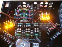
Ok. Here are a couple of photos. As you can se it looks like s...
What you cannot see with your ears is that it sounds divine despite the fact that this is so very much an alpha build
First photo show the "off" situation where the batteries are getting charged and some amber power LED's light up. They actually serve the purpose of dumping the charging voltage to what I wanted. They also dim in accordance with the degree a charge (can't really take the honor for this useful feature).
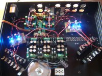
Second photo show the "on" state. There are some blue LEDs on the pre-regulated side to indicate that the rails are powered.
The rest should be pretty obvious as I have posted it before in this thread.
What you cannot see with your ears is that it sounds divine despite the fact that this is so very much an alpha build
First photo show the "off" situation where the batteries are getting charged and some amber power LED's light up. They actually serve the purpose of dumping the charging voltage to what I wanted. They also dim in accordance with the degree a charge (can't really take the honor for this useful feature
).Second photo show the "on" state. There are some blue LEDs on the pre-regulated side to indicate that the rails are powered.
The rest should be pretty obvious as I have posted it before in this thread.
Attachments
A very naive and basic question: with the SEN9018 I am doing the I/V-conversion using resistors connected on the XLR output pins.
Why not do it on the pre-amp input, or even in the power amp if the pre-amp is a current amplifier?
Is current coupled signal transmission more prone to interference than potential coupled?
Forgive me my ignorance and sorry for the OT - just trying to learn here
Cheers,
Nic
I find this an interesting topic, could we discuss it here? Any input Patrick?
Normal practice is to have a low impedance source and a high impedance load, to minimize interference and cable effect (filtering). So the I/V resistor should be right at the converter board.
Any further thoughts?
I find this an interesting topic, could we discuss it here? Any input Patrick?
Normal practice is to have a low impedance source and a high impedance load, to minimize interference and cable effect (filtering). So the I/V resistor should be right at the converter board.
Any further thoughts?
See Audio-gd ACSS based on an old Krell technology. With the Audio-gd the I/V resistor replaces the volume control either with a potentiometer or relayed attenuator (higher models.) Even on V-out DAC's the analog stage is is current steering or current mode (needing an I/V resistor.)
What I found with an ACSS integrated DAC-headamp is that the measured distortion was constant up to clipping, IOW's the FFT looked the same with 2vrms into 10k load on the rca (dac out) as it did swingin 6V's into 38 ohms (1W). So the advatage was unlike most gear the sound did't "change" as you moved the volume up/down. The problem I had with it is the DAC analog section wasn't the greatest and started with fairly high distortion (.01% THD) which for a modern wolfson based DAC (I know this isn't a current out DAC but the analog stage was) wasn't good enough for sensitive phones. For orthos it was great because pushing 1W it had the same .01% THD and distortion profile (not easy to achieve .01% THD swinging 6V into 38 ohms without NFB.)
But if you go this route the only real advantage is turning the "buffered" I/V into your volume knob using one of the relay based attenuators or a stepped attenuator with the amp in the same chassis. I believe there are proporetary tricks (powerful transimpedance analog stage) to use interconnects which most have found to be not as good as old fashioned balanced cables.
[snip] The problem I had with it is the DAC analog section wasn't the greatest and started with fairly high distortion (.01% THD) which for a modern wolfson based DAC (I know this isn't a current out DAC but the analog stage was)...[snip]
The terminology we commonly use to distinguish among DAC outputs is rather confusing.
Voltage-output DACs are pretty easy to understand: as long as the output current limits are observed, they produce code-dependent output voltages more-or-less independent of loading.
Current-output DACs usually require a rather low resistance load to meet their specifications of properly code-dependent output current. They are not usually per se current generators of anything approaching an ideal sort, where, in analogy to voltage sources, the current delivered is independent of the loading, i.e., the voltage burden.
A better description of most "current-output" DACs would be "DAC which requires a low resistance load to output the proper current". Philips for example mentions the maximum voltage that can be produced by the output current flowing in the load for some of their "current-output" DACs.
One cited reference a while back in this thread shows some of the errors that can arise for a simple R-2R ladder network DAC if not terminated in a low resistance. Granted that most modern audio DACs are not as simple, for the majority there is still a need to make the voltage swings small.
Patrick assures this in his minimalistic way by using common-gate high-transconductance JFETs running at Idss. The usual default in stock equipment is I-V converters with transresistance-configured opamps, which tend to have their own sets of problems.
Brad
If you were to build your entire audio chain (like me), and you wanted to operate in current mode, then you should go 100% current mode.
That means no R_iv, but that you use a (variable gain) current amplifier to drive the speakers in open loop.
Malcolm Hawksford has a couple of papers on the topic.
e.g. http://www.essex.ac.uk/csee/researc...J12 Distortion reduction MC current drive.pdf
It of course gets somewhat complicated when you want to use a multi-way speaker with crossovers, either before or after the current amplifier.
But then if you use the ES9018, you have 8 channels which can give you 4-way stereo.
And then you can also do all your cross over filters in the digital domain.
BIGGGGG project.
Patrick
Jan Didden has a new website for Linear Audio, and here is the link to the online article.
http://www.linearaudio.net/images/onlinearticlesPDF/didden-la -vol2euvl.pdf
I cannot thank Jan enough for his generosity to make available the article to all, free of charge.
I hope some of you would in turn support Jan and his brave undertaking, so that we can have many many more interesting articles in the future, at Linear Audio.
Cheers Jan,
Patrick
Ok for the modulating DAC's we have accepted servoe IC's for offset.
What about a leap foward and create a balanced Sen and sum the phases with an opamp. The simulations are amazing, real benefit by summing the balanced output phases, pushing distortion will below -100dB with PCM1704 current levels (including the weak 1704's output impedance.)
Also as non-linearities due to the circuits input impedance cause 2H distortion, that gets canceled as well.
Summing a balanced Sen gives THD numbers nearly as good as the new NPD1 but with Jfets which are designed for low-noise applications (i.e. the uV 20th LSB.) I mean you wouldn't design the input to a phono preamp with a mosfet.
Granted it seems counter intuitive using an opamp at all in this NFB free I/V, the summation (rather subtraction) of differential into single end is one area the opamp has been perfected for (there are better choices than showed in he sim).
There are other options but ever look at a transformer's THD below 100 hz? And I haven't seen a low distortion discrete open loop option to sum differential to unbalanced. So here is the sim to play with.
Attachments
I have no need personally to do balanced-> SE conversion, as everything I build is balanced.
Well, almost everything.
And most certainly not with an opamp.
Patrick
Not to be argumentive but at some point to reap the benefits of balanced you do a subtraction/summation. Now some wait till the speakers/drivers I guess the voice coil provides the some CMRR & distortion cancellation, it just seems a poor choice, why amplify distortion? Just curious what the alternatives out there are, I was considering possibly going balanced up to the push-pull mofsets on the power amp outputs.
Well you agree the voice coil is a poor choice to sum the differential signal.
I am no fan of opamps either but they are good at addition and subtration. We share the opinion that they are inferior for I/V. But if they are suitable for servoing dac offset with the Sen, they are even more suitable for differential to unbalanced conversion, that's what they have been optimized for the last few decades (in different aplication.)
Obviously the sim shows an advantage to a balanced Sen I/V then summed, so where do you propose the conversion to unbalanced, sound in air is not differential so has to be done somehwere prior.
I ordered a hard copy of Linear Audio Vol #2 so I can read about this design. I did some simulations of my own based on the links provided early in this thread. I was able to get an input impedance of about 1.2 ohms using bipolar transistors in the sim. The distortion is higher with bipolars though noise is about the same.
I ordered a hard copy of Linear Audio Vol #2 so I can read about this design. I did some simulations of my own based on the links provided early in this thread. I was able to get an input impedance of about 1.2 ohms using bipolar transistors in the sim. The distortion is higher with bipolars though noise is about the same.
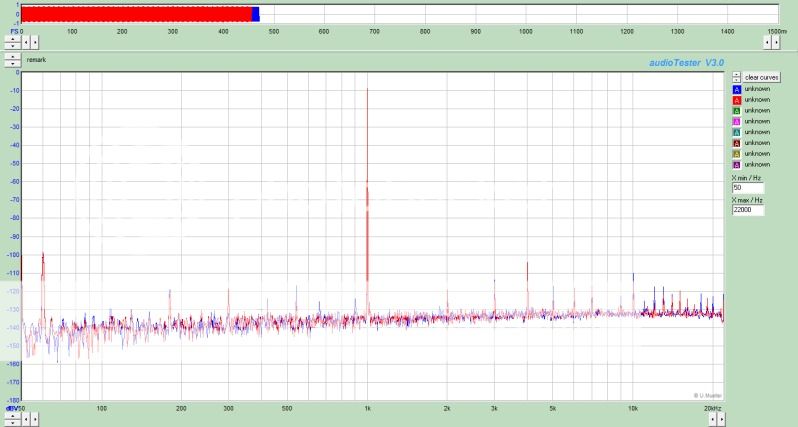
This is a FFT of a pair of paralel PCM1704's with a passive I/V of 40 ohms, a terrible scenario if you believe high input impedance (voltage compliance on the dac i-out pin) is a significan issue (in other words same a a single pcm1704 with 80 ohms i/v input resistance.) This ~100mV voltage is amplified with a discrete Jfet stage and then followed by the filtering and a diamond buffer.
This is at full 0dbs (I haven't calibrated the sero point). As you can see there is no distortion above -90 dB. I am sure your BJT sims show much higher distortion, best I have ever seen with a BJT open loop I/V is -80db . In real life with an imperfect i-dac output (the chips have inherent distortion and low output impedance) you won't come close to designing a lower distortion stage than this 40 ohm input impedance I/V design with BJT's without using feedback to the i-out pin.
I guess what I am saying is stick with the j-fet version of the SEN especially if you sim higher thd with BJT's, because the "non" linearities caused by the j-fet's 7 ohms input impedance is neglible and unimportant.
So this is proof that for the king of R to R that I/V input impedance (voltage compliance) really doesn't matter.
The goal is lowest open loop distortion without nfb on the i-out pin of he DAC chip. That most of us agree on.
I disagree with Evil and others that NFB and opamps are bad to use post I/V conversion, but we all have our opinions.
The jfet version I simulated had 15 ohms input impedance and the distortion was about 0.0005% vs. 1.2 ohms and 0.0006% thd for the BJT version. Each had S/N of about 135dB (@ 1kHz) and the same gain of 53dB. I haven't read the article so I can't comment any further. I'm not expert enough in DAC's and I/V design to say much either. Thanks for the information.
Of course the input impedance effect of distortion depends crucially on the DAC. But, as well, the circuit distortion is not due only to it. The JFET approach has the great advantage of essentially no loss of current, unlike bipolars.
Fed from a true current source that circuit works about as well as it can. IIRC Patrick tested his with Didden's AP driving a 20k resistor, which is a pretty decent approximation to a current source.
For further improvements in measured performance (whether audible or not) a bootstrapped cascode structure can be used. But then you need more voltage overall, and one has to wonder if it is worth it.
- Home
- Source & Line
- Digital Line Level
- Zen -> Cen -> Sen, evolution of a minimalistic IV Converter