I made some cable by hand - 3 cores braided, aluminium foil shield, copper braid around the foil, PVC heatshrink tubing outside.
Same connection strategy as with the usb cable before and I haven't changed anything else.
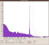
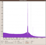
It sounds good again but 2nd harmonic is also back up (by 36dB!) to -100dB 3rd harmonic is down from -87.7dB to -91.6dB.
Not really sure what's going on. Could twisting DAC +ve and -ve together prevent the balanced circuit from canceling out the 2nd harmonic properly?
Its seems that the 2H is probably closer to reality, maybe the earlier measurement was a fluke ?
If you read the article at Jan Didden's website, you will know that we had a hard time measuring the circuit to -120dB (or 2.8µV).
And that was with an AP System1 in balanced mode.
So when people reporting measuring to -130dB or even -140dB, they might have super professional equipment that none of us have.
")
Patrick
And that was with an AP System1 in balanced mode.
So when people reporting measuring to -130dB or even -140dB, they might have super professional equipment that none of us have.
Patrick
Its seems that the 2H is probably closer to reality, maybe the earlier measurement was a fluke ?
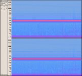
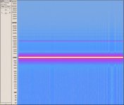
No fluke - there is second harmonic in each measurement of the two halves of a balanced pair and it clearly cancels out when they are mixed together. See attached pictures.
So the total circuit DAC - Sen - ADC in balanced mode definitely had very low 2nd harmonic with the usb cables.
I saw this on all the measurements with the usb cables and I did at least 4 or 5 - it varied a bit, sometimes I could see a little spike at around -130dB.
Attachments
If you read the article at Jan Didden's website, you will know that we had a hard time measuring the circuit to -120dB (or 2.8µV).
And that was with an AP System1 in balanced mode.
So when people reporting measuring to -130dB or even -140dB, they might have super professional equipment that none of us have.
Patrick
I'm not claiming to be able to measure the distortion from the Sen circuit in isolation, I'm just reporting the numbers of the overall chain.
The components in the chain might be conspiring together to cancel out distortion but the end-to-end result is pretty clear in the digital data as you can see from my previous post.
My ADC is a PCM4220 and I was doing FFTs with 10M samples using Audacity.
Not much progress this weekend - I tried increasing Riv but my circuit gets too hot with Riv > 256R. I'm not sure whether I just need to add heatsinks to make it work or if it's heating up because increasing Riv is causing it to oscillate (perhaps a problem with the servo which was working really well with Riv=256R).
I did get some more measurements with increased Riv in the window before it becomes unstable with a lower noise floor which you aren't likely to believe either
In earlier posts (post 421) Joachim has recommended using blue BLOCK split bobbin pcb transformers In noise sensitive enviorment
Has anyone actually made a non-battery PSU for Sen that they are happy with?
Patrick> next project should be a hassle-free, plug and forget LiFePo4 charging scheme
I don't use them, so there ain't going to be one any time soon.
One reason is that they have limited lifetime, even unused.
My current preamp NiMHs are from 2007, and they are still fine.
Patrick
what do you think bout his battery PSU from
THEL AUDIOWORLD
Akkunetzteile für Audio-Module
Zoran
We have a number of PM's asking us for the same thing -- how to do SEN for PCM1704.
As you can download the article from Linear Audio, you will find that the SEN was designed originally for PCM1704.
Thus, you will need the standard evaluation kit, and 4x of matched quads 2SK170BLs. (i.e. totally 16 JFETs).
Alternatively, you can also use 2x (or 4x if you want lower Zin) of matched quads of2SK369V.
We do not sell matched 2SK170BLs. But you can get them from Spencer.
The rest you can get from us.
All you need to do is download the service request form and fill it in.
Then send it to Gogowatch and he will process for you.
xen-audio
xen-audio
The content of the evaluation kit are listed at the beginning of this thread in post #3.
We have everything in stock.
All information required are public. Please help yourself.
Regards,
Patrick
Last edited:
Hi Patrick
This is my first post here, but I’m well on the way to assembling all the parts I need to build a 2SK369 based SEN to use with my Twisted Pear Buffalo II ESS9018 based DAC.
Nic has kindly provided me with a set of closely matched FETs. At the moment I’m using a Twisted Pear Legato I/V stage (a little modified) and its op amp–based balanced to single ended converter to feed my single ended valve preamp. Rather than use the Bal to SE converter with SEN, I’ve decided to fit Jensen JT-11P1 input transformers to my preamp. Properly terminated, these will provide an ideally balanced- much better than an op amp, as discussed in a white paper on the Jensen website- low distortion input. (I’ll also use them on my SE inputs, where their superb CMRR should provide additional sonic benefits.)
But, of course, I need to avoid applying any dc to the Jensens. Nic’s matching will win half the battle here. But I’m concerned about using a reference voltage of ½ Vacc (1.65 V). Unless I’m mistaken, the 681k/470k voltage splitter you propose will only result in 0 V (analogue ground) on the output when the floating supply is exactly 18 V. In practice, with NiMH batteries, the supply voltage will be vary from 16.8 V to 14.4 V (your data) as the batteries discharge, resulting in a small but increasing dc voltage on the output, relative to ground. Now, if the power supplies to both SENs which form the two halves of the balanced I/V converter for the ESS9018 discharge at the same rate and from the starting point, there will be no dc on the combined output- but can we rely on this, and, in any case, won’t there be a small dc current through the each I/V resistor?
I notice that Russ White of Twisted Pear has abandoned the practice of using a ½ Vacc reference; in the latest Legato circuit, the DACs see 0V instead, with supposedly no performance deficit (I think ESS feel the same way). So, unless I’ve got this wrong (and all this only just occurred to me!) it might be best to use a zero V reference for SEN- ESS9018 too, with two 680k (or whatever) in the voltage divider? Then all my concerns vanish- if the Fets are well matched.
A couple of other things. Why do you favour using bipolar caps for C1 and C2, rather than polar electroytics? And would you agree- initially at least- I would be best to omit any I/V low pass capacitor, as the Jensen transformer itself rolls off above 95 kHz?
Finally- even though I’ve yet to try it- many thanks for your elegant design!
Paul Needs
I don't have a working ES9018, so I am the wrong person to answer your questions relating specifically to that.
If you want to place the ES9018 i_out at 0V instead of Vcc/2, my understanding is that you will need an offset current.
This has also been done for the likes of TDA1541, but you will still have an offset drift problem.
If you want to have stable voltage, you can apply a voltage regulator after the batteries.
If you are worried about the transformer seeing DC, you can always use a coupling cap.
I am not particular fond of either, but this is my prejudice.
Hope I answer your questions in suffucuent detail.
Patrick
Hi Paul,But I’m concerned about using a reference voltage of ½ Vacc (1.65 V). Unless I’m mistaken, the 681k/470k voltage splitter you propose will only result in 0 V (analogue ground) on the output when the floating supply is exactly 18 V. In practice, with NiMH batteries, the supply voltage will be vary from 16.8 V to 14.4 V (your data) as the batteries discharge, resulting in a small but increasing dc voltage on the output, relative to ground. Now, if the power supplies to both SENs which form the two halves of the balanced I/V converter for the ESS9018 discharge at the same rate and from the starting point, there will be no dc on the combined output- but can we rely on this, and, in any case, won’t there be a small dc current through the each I/V resistor?
I was worried about the same thing, but in practice I found the problem to be limited. While experimenting with higher voltages (3x 9V NiMH battery) I did not care to change the resistor values and the DC-offset only changed by 2-3 mV. Although I did not hear any immediately improvement with higher voltage I will be using 3x 9V and a simple regulator circuit between batteries and the SEN. As I already had to build the charging circuit adding in the regulator was easy.
Cheers,
Nic
Hi Nic
did you check for dc across the IV resistor? What sort of V regulation are you considering?
Hi Patrick
Thanks for your reply. I realise that your circuit was perfectly designed for its original application, and it's mostly Nic's -and now- me that have pushed the issue of its application to an ESS9018! Your efforts are much appreciated. I can't find any further info on the 9018's reference requirements, and my knowledge of electronics, especially anything tending towards the digital, is patchy. I've no doubt that you've forgotten much more than I've ever known! Hence my questions.
Does anyone else know anything about this?
In the meantime, I'm inclined to play it safe, and use a 1/2 AVCC reference, together with voltage regulators after the batteries. I'm going to use 330R IV resistors. From the Twisted Pear website-
“(In stereo mode) each analogue output at 0DBFS is equivalent to a voltage of approximately 92.4% of AVCC in series with 195R. So given 3.3VDC AVCC it will be about 3.05Vpp across 195R. The output will be DC biased at AVCC/2. This works out to about 16ma peak to peak at each output. The amount of bias current will depend on the voltage of the virtual ground”.
So V out at 0DBFS will be about 1.9 V rms. So again, a couple of questions, the first for Patrick, the second for anyone-
I have some very high performance 15 V low noise series regulators to regulators to hand (Paul Hynes S1715LN and S3715LN types). Would SEN performance be seriously degraded if I used 15 V floating supplies?
I have three + (15V) regulators, and three -(15 V) regulators. As the supplies are floating, I don’t see any reason why I shouldn’t use two of each for each channel- say +ve for the DACA (+) output circuit, and –ve for the DACB (-) output. Or am I missing something?
All help very much appreciated
Paul N
Hi Nic
did you check for dc across the IV resistor? What sort of V regulation are you considering?
Yes, DC measured over the IV resistors, but also between the two phases.
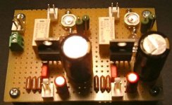
For the moment I'm using some LT3080 regulators (suggested by Patrick) that I wanted to try out. The charger/regulator circuit works a charm. A cheap 32V 2.5A SMPS (HP printer), power led's to dump the voltage and give a visual readout of charge level, relays, 3x 9V NiMH batteries, the LT3080 regulators (set to 22.5V) and a small BG on the output. Works a charm!
I have some 18V PH series regulators that would work fine but their caps are only 25V rated and I have other plans for these.
Nic
Attachments
Hi
Nic,
thanks for that. I'll send a PM to see what else you've been up to, before I spend any more money
But- anybody- what about my other questions-
"I have some very high performance 15 V low noise series regulators to regulators to hand (Paul Hynes S1715LN and S3715LN types). Would SEN performance be seriously degraded if I used 15 V floating supplies?
I have three + (15V) regulators, and three -(15 V) regulators. As the supplies are floating, I don’t see any reason why I shouldn’t use two of each for each channel- say +ve for the DACA (+) output circuit, and –ve for the DACB (-) output. Or am I missing something?"
Best wishes
Paul N
JFET needs voltage, else they get into a highly non-linear region for their capacitances.
I normally use 9V as minimum per FET for the likes of 2SK170 / 2SJ74.
Would 7.5V work? Most probably yes.
Does it sound much worse? I don't know.
Maybe you can persuade Nic to try for you.
If you want to use a regulator for the SEN, I recommend you use the Salas Shunt.
(And I am aware of the Hynes products).
Patrick
Hi Patrick
The relationship between input capacitance and supply voltage is one of my patches of ignorance I referred to. OK, I'll stick to 18V.
The main reason I thought 15 V might be OK was based on the supply often proposed here- 12 (AAA) NiMH batteries in series? Nominally 18 V, but actually 14.4 - 16.8 V, depending on charge level. (I also use Pass B1 type buffers- the same arrangement of two 2SK170BL's, but used as source followers- with 15 V supplies after my present IV circuit. But here, the input capacitance is less critical)
I proposed series regs, rather than shunt because of the batteries- lower current required. The LT3080 Nic mentioned looks interesting- relatively cheap, good bandwidth and low noise, and they see constant current loading, presumably making their task easier
Best wishes
Paul N
The relationship between input capacitance and supply voltage is one of my patches of ignorance I referred to.
OK, I'll stick to 18V. The main reason I thought 15 V might be OK was based on the supply often proposed here- 12 (AAA) NiMH batteries in series? Nominally 18 V, but actually 14.4 - 16.8 V, depending on charge level. (I also use Pass B1 type buffers- the same arrangement of two 2SK170BL's, but used as source followers- with 15 V supplies after my present IV circuit. But here, the input capacitance is less critical)
I proposed series regs, rather than shunt because of the batteries- lower current required. The LT3080 Nic mentioned looks interesting- relatively cheap, good bandwidth and low noise, and they see constant current loading, presumably making their task easier
Best wishes
Paul N
JFET needs voltage, else they get into a highly non-linear region for their capacitances.
I normally use 9V as minimum per FET for the likes of 2SK170 / 2SJ74.
If you want to use a regulator for the SEN, I recommend you use the Salas Shunt.
(And I am aware of the Hynes products).
Patrick
have you tried Salas shunt with Sen or anything else, are you happy, which Salas shunt - hypno or BIB
- Home
- Source & Line
- Digital Line Level
- Zen -> Cen -> Sen, evolution of a minimalistic IV Converter