yes, it will be really quite interesting putting the NTD1 (opc) (only the mosFETs, caddock to220, TX220Z zfoils and auricap/vcap CuTF in the signal) against the SEN/CEN. They are 2 simple (although in the rather extreme case of the NTD1 it requires serious commitment due to size and heatsinking) and both are circuits with very few parts and a rather pure modus.
NTD1 measures about 15db better in THD+N in this form, but i'm looking for sonics, which are superb on the NTD1, so something smaller/less awkward that approaches or equals but slightly different is what i'm after for the tweeter dac. i'm not looking to replace the D1, so the comment of people unhappy with their sabre IV stages doesn't hold for me. I'm using one of several choices including the SEN/CEN to run the DAC->AMP->tweeters section of my system, with the NTD1 running the mid bass->mid.
NTD1 measures about 15db better in THD+N in this form, but i'm looking for sonics, which are superb on the NTD1, so something smaller/less awkward that approaches or equals but slightly different is what i'm after for the tweeter dac. i'm not looking to replace the D1, so the comment of people unhappy with their sabre IV stages doesn't hold for me. I'm using one of several choices including the SEN/CEN to run the DAC->AMP->tweeters section of my system, with the NTD1 running the mid bass->mid.
Last edited:
Guess this is what Calvin was referring to :
http://www.diyaudio.com/forums/digital-source/6121-easy-build-i-v-stage.html
Patrick
He said improved Jocko, I believe that is the non-improved Jocko.
I guess my issue with J-fet designs is the high input impedance. Reports are coming in good with the Cen using the PCM1704, a chip which I have dived deep into and know that it is adding significant distortion with less than a 10 ohm load.
All I am saying is if the PCM1704 sounded good with this high of an input impedance I/V, the Cen must be pretty damn good. But probably a better match for PCM56/58/63 which aren't as touchy.
Hi,
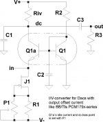
actually I was referring to a simpler Jocko as in the attachment. I called it ´improved´as the THD-values for this simple version were reported to be less good, possibly not better than -60dB at 0dBfs.
Indeed fell the first testands into that range and I started to tune and tweak. Now my versions are consistant at -90dB and better (measured at the output of the associated JFET-bufferstage and 0dBfs).
The CCS towards the positive supply is omitted with and the Riv is used instead.
C1 limits the bandwidth. In conjunction with C2 the input impedance of the circuit may be linearized up into the MHz range.
J1 is a simple NJFET-current sink. Its current taking over the DACs offset current plus the bias current of Q1a. Its bias may be tuned by P1, thereby setting the dc-working-point at the same (influence on THD-values too). C3 blocks dc and couples the audio signal to the following (buffer-)stage. If R3 is rather large in value as it could be as the Gate-resistor of a JFET-bufferstage, C3 may be small in value (and size). The current through Q1 is set by the value of R2. Tuning of R2 allows to null the input offset at Q1a´s emitter.
The quality of the supply voltages needs to be high, since the positive PSRR is low. But then we need quality supplies in audio anyway. ;-)
Against the before linked Jocko with its two bipolar CCS setting the working points is very easy and the circuit is lower in noise (and seemingly also lower in THD).
The circuit resembles certain similarities to the D1 and OPCs Power-MOSFET version of the D1, but requires less effort regarding power consumption, heat dissipation, size, high values of supply voltages, sourceability of parts and cost. Using easy to source matched dual transistors no further matching is required. A solder station and a DVM to control the dc-working point is all whats needed to get the thing running.
jauu
Calvin
Attachments
Last edited:
Actually same problem as the Pass Zen IV -- no PSRR and coupling cap in voltage mode.
But indeed very simple.
Patrick
Much lower distortion than Pass Zen, much lower input impedance. Zen really measures like a passive I/V+ tube stage but with better S/N.
Coupling cap is a coupling cap, my guess is he probably has a dc coupled buffer figured out.
As to other circuits.
We have our own version of all.JFET D1, and the Hawsford as you mentioned.
They do not offer any sonic advantages but are much more complicated.
And the CEN / SEN are dead quiet !!!
As said, we use SEN ourselves for PCM1704.
Patrick
Patrick
have you build this http://www.diyaudio.com/forums/pass-labs/34191-i-u-stage-d1-clone-2sk389-finetuned.html
for me It Is step ahead over original D1 I/V
your comments please
I don't have a Spencer D1. I have my own version of a similar all JFET IV which has no coupling cap but split rails.
It has the same input impedance as SEN, but quite a bit more distortion, even though mostly 2nd harmonics.
And it is also more complicated (7 JFETs) and requires a (additional JFET) servo.
So the choice is simple.
There is no point in asking me which sounds better than which.
This is something everyone has to decide for himself.
And the IV is only one component in an entire audio chain.
So I shall not make such comments or statements, except to tell you what we choose for our own use.
Patrick
Hi fellas,
Patrick you mention that you use SEN for PCM1704. I currently use Spencers D1 IV on a PCM63 (Balanced) DAC. Did you find the SEN better than the Spencer D1?
I did not like the spencer D1 for PCM63k, easily beaten by a simply 50 ohm i/v resistor plus quiet (ccs/led/shunt PS) 6n6p anode follower where I actually had a switch to compare the two side by side level matched (which isn't saying much for the spencer d1 at all.) This was a case where the tube (hybridish) had lower THD than SS!
I guess Spence D1 and the Zen predudiced me against I/vs's. I mean if the input impedance is as high as a passive resistor I/V, and the linearity is worse than a tube?
The best performing I/V for the PCM1704 I have is a BJT with 27db nfb followed by a diamond buffer all dc coupled (its commercial.) And I do think that a minimalist concept like the CEN is worth a serious look (but again the PCM1704 hates an I/V with input impedance over 10.)
But the Cen certainly demands a try for me with the Jfets (especially the ouput transformer option.)
Hello,
If one wanted to use a regulated power supply, would that be a problem? My dac already has one available at 15v (see image but 15v zeners). Or is this circuit so sensitive that battery power is mandatory? (asking since I'm still waiting for my Linear Audio issue ordered a while ago)
Thanks
If one wanted to use a regulated power supply, would that be a problem? My dac already has one available at 15v (see image but 15v zeners). Or is this circuit so sensitive that battery power is mandatory? (asking since I'm still waiting for my Linear Audio issue ordered a while ago)
Thanks
Attachments
Last edited:
I have read the posts #150 on regarding floating supplies. I'm a newbie in regards to floating supplies.
I suspect that even if my supply was isolated from the rest of the circuit ground and I used only +15v and 0v there would be leakage to ground via the mains transformer. Is that so?
I suspect that even if my supply was isolated from the rest of the circuit ground and I used only +15v and 0v there would be leakage to ground via the mains transformer. Is that so?
I too, looked at the idea of floating supplies, shunt regs, etc and considering that you need a dedicated 18v supply for each Cen/Sen stage, it quickly became a problem in itself
And, I wasn't happy with the voltage developed across the Riv also being superimposed on the supply lines, regulator, caps, transformer secondary, etc - just asking for signal degredation
Take a look at the world of batteries, particularly those Li-ion ones intended for remote controlled cars, helicopters, etc (Patrick himself uses a system of the 9 volt block batteries with isolating relays for recharging ) - this appears a simpler, possibly better, supply solution.
..... just my 2 cents, mind you.
Lithium batteries, especially the ones with unmeasureable output impedance and noise (LiPO4 and other variants) are a huge untapped new frontier for DAC's, both on the digital and analog side. But setting up the automated charging circuit is a PIA ") I've found one of the biggest problem with dealing with low level signals is the power company and rectifiers, take a scope to your wall outlet and study it over the course of a day, its amazing we get any quality audio at all from household mains. I work with robots and vfds in my real job and you wouldn't believe all the issues from poor quality mains.
I've found one of the biggest problem with dealing with low level signals is the power company and rectifiers, take a scope to your wall outlet and study it over the course of a day, its amazing we get any quality audio at all from household mains. I work with robots and vfds in my real job and you wouldn't believe all the issues from poor quality mains.
So taking the jump into the new battery technology is well worth the trouble, just don't make them explode
I've found one of the biggest problem with dealing with low level signals is the power company and rectifiers, take a scope to your wall outlet and study it over the course of a day, its amazing we get any quality audio at all from household mains. I work with robots and vfds in my real job and you wouldn't believe all the issues from poor quality mains.So taking the jump into the new battery technology is well worth the trouble, just don't make them explode
With a PCB and all parts ready, you'll get this going within an hour using 8x 9V alkaline batteries for two balanced channels. They will give you more than 10 hours listening. And when after 10 hours, you are still pleased with the results, then it's the time to start worrying about charger circuits, filtering caps, regulators, ..... But then again you may enjoy the music so much that you won't want to bother with regulators and what not any more.
So why worry about it now ?
One step at a time,
Patrick
So why worry about it now ?
One step at a time,
Patrick
regal,
With due respect and my limited knowledge I fail to grasp how power supplies would be a problem in a digital circuit. My PC has a 50$ 500w supply and has not missed a single 'bit' ever running at 3Ghz 24hrs/day for 2+ years now, hence I would say the power supply is ample able to deal with mains noise etc.
In low level analog circuits, that is a different story.
- Home
- Source & Line
- Digital Line Level
- Zen -> Cen -> Sen, evolution of a minimalistic IV Converter